
Merkur Xr4ti L4-140 2.3L SOHC Turbo (1985)
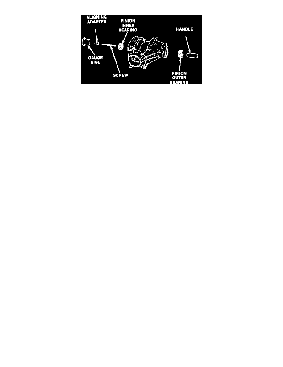
Fig. 2 Installing depth tools
AXLE ASSEMBLY
1.
Lubricate pinion bearings with suitable grease.
2.
Assemble pinion bearings and dummy pinion depth tools into rear axle case as shown in Fig. 2. Ensure gauge screw is tight in the gauge disc
before assembling the tool.
3.
Hold gauge disc stationary and gradually tighten the tool handle until a rolling torque of 14-18 inch lbs. is measured at the pinion depth tool
handle. Before conducting the rolling torque check, turn tool shaft ten times to seat the bearings. Any time the tool is loosened or
tightened, rotate the pinion ten times before another rotational torque check is made.
4.
Position pinion depth gauge tool tube T85M-4020-A1 or equivalent into case. Ensure tube gauging surface is aligned with gauge disc, then install
bearing carriers. The bearing carriers must be installed in their original case bores and without the O-ring seals.
5.
Thread the bearing carriers evenly into the case. When the carriers contact the gauge tube, snug them down to remove all endplay from the tube.
The carriers are properly tightened when a moderate amount of effort is required to turn the gauge tube by hand.
6.
From the available selective pinion depth shims, determine the clearance between the gauge tube and gauge disc. The correct shim thickness has
been determined when a slight drag is felt between the shim and gauging surfaces.
7.
The clearance check in step 6 has determined the pinion depth shim thickness for a nominal or zero variance pinion. To determine if this is the
correct shim thickness, inspect the pinion shaft for a pinion variance marking and proceed as follows:
a. If the pinion shaft does not have a variance marking, a pinion variance calculation is not necessary.
b. If the pinion shaft has a minus pinion variance marking (1 to 3), measure the shim from step 6 with a micrometer to determine its thickness.
From this measured thickness, add .0004 inch (.01 mm) for a minus 1 marking, .0008 inch (.02 mm) for a minus 2 marking or .0012 inch (.03
mm) for a minus 3 marking depending upon the pinion variance marking.
c. If the pinion shaft has a positive pinion variance marking (+1 to +3), measure the shim from step 6 with a micrometer to determine its
thickness. From this measured thickness, subtract .0004 inch (.01 mm) for a positive 1 marking, .0008 inch (.02 mm) for a positive 2 marking
or .0012 inch (.03 mm) for a positive 3 marking depending upon the pinion variance marking.
8.
Install inner pinion bearing. Ensure pinion depth shim is in position on the pinion shaft before installing the bearing.
9.
Install a new collapsible spacer onto pinion shaft.
10.
Position pinion into case and install the outer bearing. Lubricate the bearings before installing the case.
11.
Install the pinion nut.
12.
To preload the pinion bearings, gradually tighten the pinion nut. Each time the nut is tightened, check the pinion shaft rolling torque (bearing
preload), using an inch lb. torque wrench. Continue tightening the pinion nut in small increments until a rolling torque of 14-18 ft. lbs. is measured
at the pinion shaft. An increasing resistance will be felt as the pinion bearing preload is increased by the action of the collapsible spacer. If
the nut is tightened beyond the specified rolling torque, remove pinion and install a new collapsible spacer and repeat step 12.
13.
Stake pinion nut to the pinion shaft.
14.
Install pinion seal.
15.
Install pinion flange and attaching nut. Torque attaching nut to 95-110 ft. lbs.
16.
Position differential assembly into case.
17.
Install new O-rings onto bearing carriers and position carriers into their original positions. Lubricate the bearing carrier threads and O-rings with
the correct axle lubricant before installing case.
18.
Using a suitable tool, turn bearing carriers into axle case until they lightly seat against the differential bearings. This seating action can be felt as
the bearing carrier cups contact the differential bearings. When the bearing carrier O-rings enter the case, the turning effort will increase.