
Milan L4-2.3L VIN Z (2006)
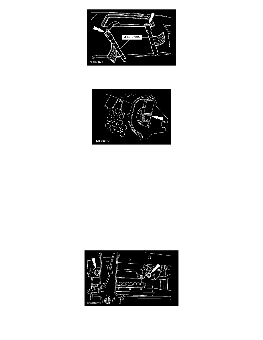
15. NOTE: Fusion and Milan shown, Zephyr similar.
Remove the restraint system diagnostic tools from the passenger air bag module electrical connectors.
16. CAUTION:
-
Do not install the passenger air bag module electrical connectors by the locking buttons. Damage to the locking buttons can occur.
-
The passenger air bag module electrical connector locking buttons must be in the released position when the connector is being
installed, or connector damage may occur.
-
The passenger air bag module electrical connectors are unique and cannot be reversed when connected to the passenger air bag
module. Match the electrical connector key to the keyway in the passenger air bag module. Do not force the electrical connectors into
the passenger air bag module.
NOTE: RH side shown, LH similar.
With the locking buttons released, install the passenger air bag module electrical connectors fully into the passenger air bag module and seat the
locking buttons.
Zephyr
17. CAUTION: Do not handle the passenger air bag module by grabbing the edges of the deployment door.
NOTE: During air bag module installation, make sure all the deployment door clips are fully seated in the I/P.
Install the passenger air bag module into the I/P.
18. Through the glove compartment opening, install the 2 passenger air bag module bolts.
-
Tighten to 8 Nm (71 lb-in).