
Milan FWD L4-2.3L (2008)
5. Gain access to connector 925 in the left A-pillar. Refer to online WD, Section 124-1 for links to location and connector views.
6. Identify circuits VMN02 (WH-BN), RMN02 (VT-BN), and DMN07 (shield) from C925. Cut the three circuits on the female side of the connector
(17K745 harness).
7. Identify circuits CBP41 (BU) and GD133 (BK) from C925.
8. Splice the five jumper harness wires into the following circuits:
^ Blue jumper harness wire to CBP41 (BU) and any black jumper harness wire to GD133 (BK).
^
Ensure original circuits remain connected in splice.
^
Yellow jumper harness wire to VMN02 (WH-BN) and remaining black jumper harness wires to RMN02 (VT-BN) and DMN07 (shield).
^
Only splice into the cut wires heading in the direction of the connector. Tape off and secure the other cut wire ends as they are no longer used.
9. Attach the microphone connector to the jumper harness connector.
10. Bundle and tuck the remainder of the microphone cable above the front of the headliner.
2009 MKS
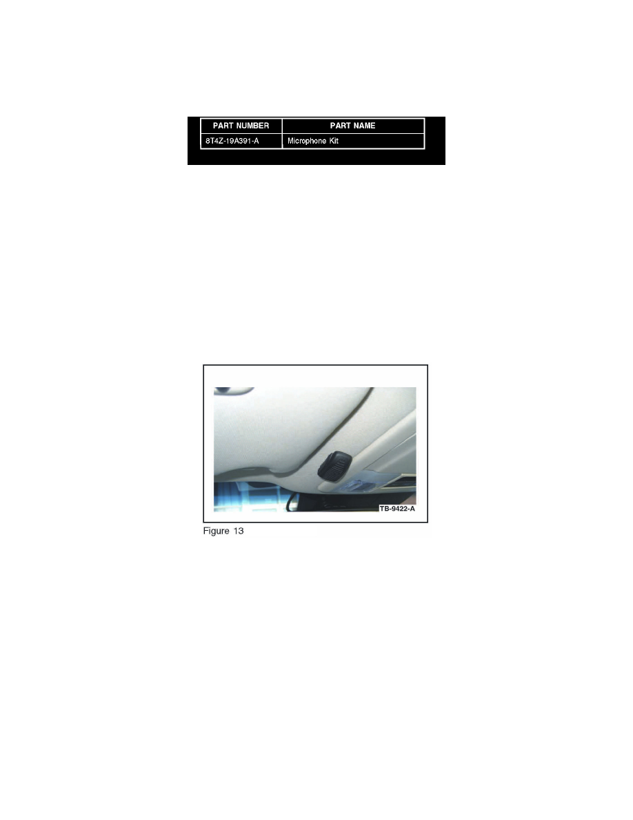
1. Remove the protective backing from the adhesive on the microphone and attach the microphone as shown in the illustration. (Figure 13)
a. Firmly press the microphone into place.
b. Ensure the microphone is parallel and adjacent to overhead console trim.
2. Lower the overhead console. Refer to WSM, Section 417-02 for additional information.
3. Route microphone cable through existing hole in the headliner, and out the front of the headliner above the rear view mirror.
4. Install overhead console; ensure microphone cable enters the overhead console trim directly behind microphone as shown.
5. Gain access to connector 911 at the rear view mirror. Refer to the online WD, Section 124-1 for links to location and connector views.
6. Identify circuits VMNO2 (WH-BN), RMN02 (VT-BN), and DMN07 (shield) from C911. Pull back the black harness sleeve and cut the three
circuits near C91 1 or if equipped with a headlamp control module-2 (HCM-2), remove the HCM-2 access cover and cut circuits under trim cover.
Refer to WSM, Section 417-01 for additional information.
7. Identify circuits CBP41 (BU) and GD133 (BK) from C911.