
Milan FWD L4-2.3L (2008)
10. If equipped, remove the 7 screws and the underbody cover.
Vehicles equipped with manual transaxle
11. Remove the 2 bolts and position the clutch slave cylinder aside.
^
To install, tighten to 22 Nm (16 lb-ft).
Vehicles with secondary air injection (AIR)
12. Disconnect the secondary air injection (AIR) pump electrical connector.
13. Remove the 3 bolts and position the AIR pump aside.
^
To install, tighten to 30 Nm (22 lb-ft).
14. Disconnect the vacuum hose from the intake manifold.
All vehicles
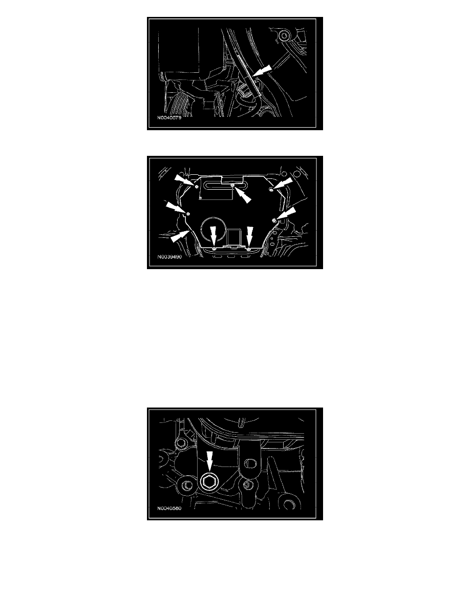
15. Detach the radiator hose retaining clip from the intake manifold.
16. Remove the intake manifold lower bolt.
^
To install, tighten to 18 Nm (13 lb-ft).
17. Disconnect the manifold absolute pressure (MAP) sensor electrical connector.
18. Disconnect the intake manifold runner control (IMRC) actuator electrical connector.
19. Disconnect the engine oil pressure (EOP) switch electrical connector.
^
Detach the wiring harness pin-type retainer and position the wiring harness aside.
20. Remove the nut and the S-terminal wire from the starter.
^
To install, tighten to 12 Nm (9 lb-ft).
21. Disconnect the throttle body (TB) electrical connector.