
Milan FWD L4-2.3L (2008)
2. Remove the wheel and tire.
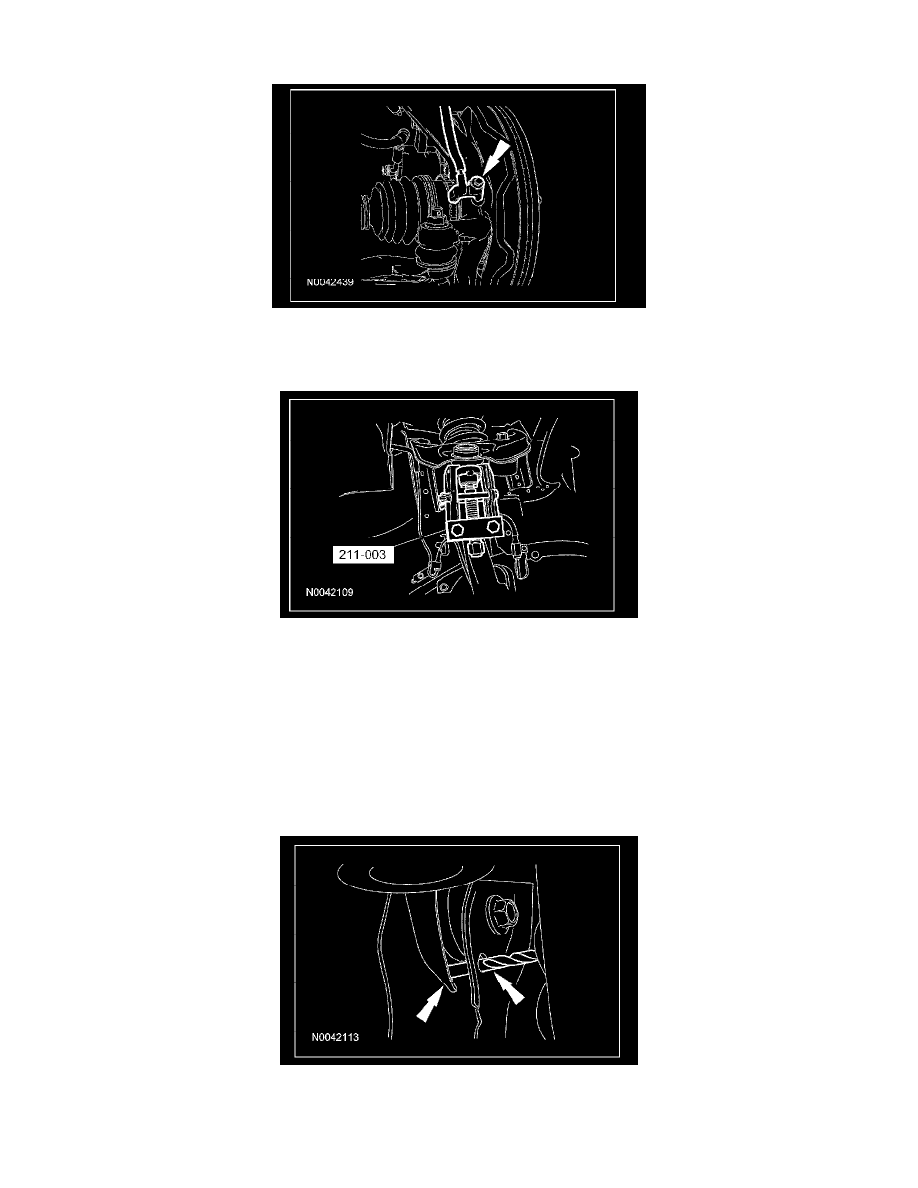
3. If equipped, remove the wheel speed sensor bolt.
4. If equipped, remove the wheel speed sensor harness bolt and position the wheel speed sensor aside.
5. Remove and discard the upper ball joint nut.
6. Using the special tool, separate the upper ball joint from the wheel knuckle.
7. Position the shock absorber and spring assembly toward the wheel knuckle to access the upper arm-to-body bolts.
8. Remove the 2 upper arm-to-body bolts and the upper arm.
^
Discard the bolts.
Installation
1. NOTE: Do not tighten the upper arm-to-body bolts at this time.
Position the upper arm and install the 2 upper arm-to-body bolts.
2. Set the upper arm bushing fastener tightening position by aligning the hole in the upper arm with the hole in the body bracket and inserting a 6.35
mm (0.25 in) drill bit through both holes.
3. Tighten the upper arm-to-body bolts to 55 Nm (41 lb-ft) and remove the drill bit.
4. Position the shock and spring assembly and install the 3 shock upper mount nuts.
^
Tighten to 30 Nm (22 lb-ft).