
Milan FWD L4-2.3L VIN Z (2007)
E3-E4
Normal Operation
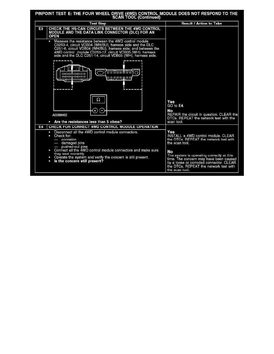
The 4WD control module communicates with the scan tool through the high speed controller area network (HS-CAN). Circuits VDB04 (WH/BU)
(HS-CAN +) and VDB05 (WH) (HS-CAN -) provide the network connection to the 4WD control module. The 4WD control module shares the
HS-CAN with the powertrain control module (PCM), the transmission control module (TCM), the anti-lock brake system (ABS) module, the restraints
control module (RCM), the occupant classification sensor module and the instrument cluster. Voltage to the 4WD control module is supplied by
circuits CBP19 (BN/WH) and SBP15 (WH/RD). Ground is supplied by circuit GD126 (BK/WH).
Possible Causes
-
Fuse
-
Circuit CBP19 (BN/WH) open
-
Circuit GD126 (BK/WH) open
-
Circuit SBP15 (WH/RD) open
-
Circuit VDB04 (WH/BU) open (HS-CAN +)
-
Circuit VDB05 (WH) open (HS-CAN -)
-
4WD control module
Test F: The Occupant Classification Sensor Module Does Not Respond To The Scan Tool
PINPOINT TEST F: THE OCCUPANT CLASSIFICATION SENSOR MODULE DOES NOT RESPOND TO THE SCAN TOOL