
Milan FWD V6-3.0L (2010)
-
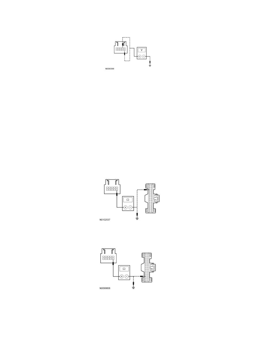
Connect: Negative Battery Cable.
-
Ignition ON.
-
Measure the voltage between the auto-dimming interior mirror C9030-2, circuit VMC30 (BU/GY), harness side and ground; and between the
auto-dimming interior mirror C9030-6, circuit VMC31 (GY/BU), harness side and ground.
-
Is any voltage present?
Yes
REPAIR the circuit in question. CLEAR the DTCs. REPEAT the self-test. TEST the system for normal operation.
No
GO to A11.
-------------------------------------------------
A11 CHECK THE COMPASS (+) COMMUNICATION CIRCUIT FOR AN OPEN OR SHORT TO GROUND (VEHICLES WITHOUT
VIDEO MIRROR AND WITH SYNC)
-
Ignition OFF.
-
For non-Hybrid vehicles, measure the resistance between the auto-dimming interior mirror C9030-6, circuit VMC31 (GY/BU), harness side and
the IPC C220-24, circuit VMC31 (GY/BU), harness side; and between the auto-dimming interior mirror C9030-6, circuit
VMC31 (GY/BU), harness side and ground.
-
For Hybrid vehicles, measure the resistance between the auto-dimming interior mirror C9030-6, circuit VMC31 (GY/BU), harness side and the
IPC C220-16, circuit VMC31 (GY/BU), harness side; and between the auto-dimming interior mirror C9030-6, circuit
VMC31 (GY/BU), harness side and ground.
-
Is the resistance less than 5 ohms between the auto-dimming interior mirror and the IPC, and greater than 10,000 ohms between the
auto-dimming interior mirror and ground?
Yes
GO to A12.