
Milan FWD V6-3.0L (2010)
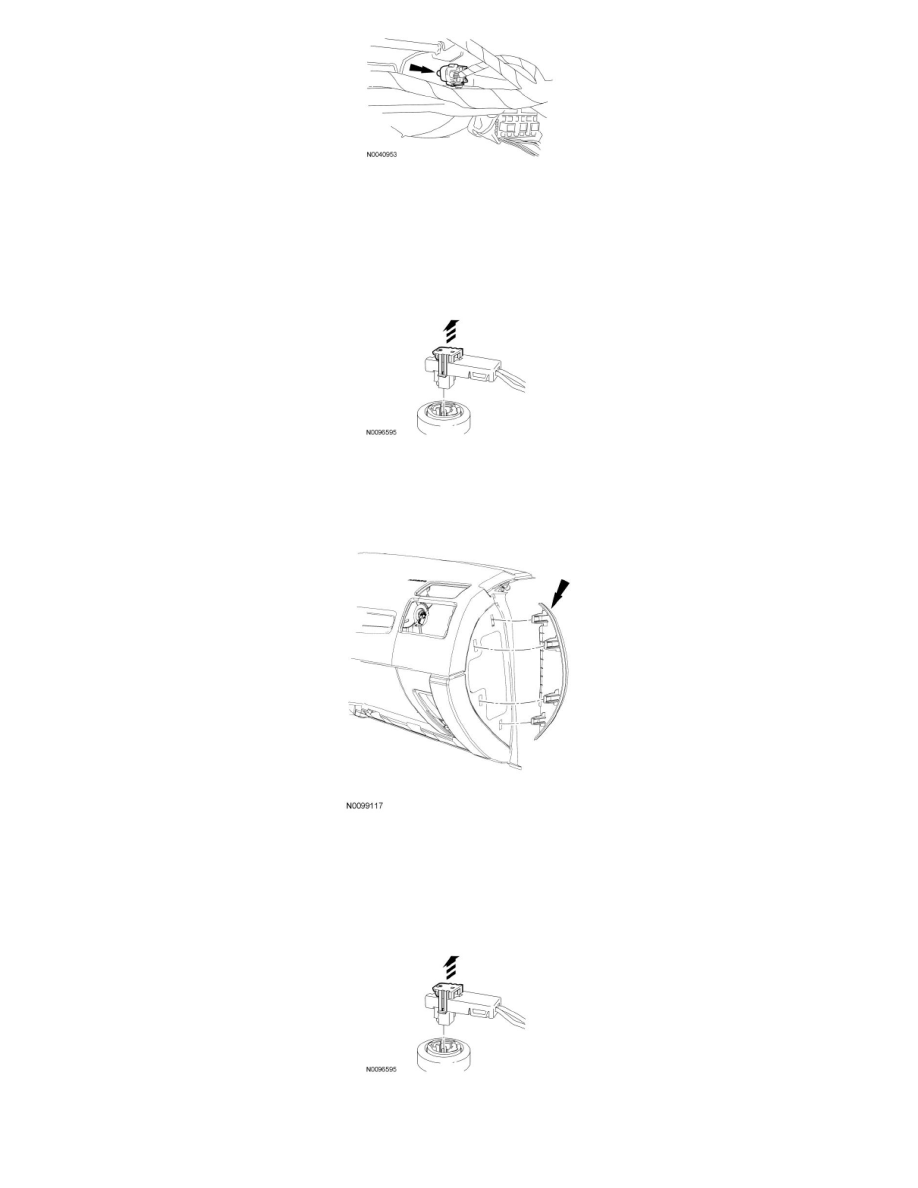
11. NOTICE: The Connector Position Assurance (CPA) clip must be in the released position before installing the electrical connector.
Failure to have the CPA clip in the released position may break the tabs on the clip causing DTCs to set in the Restraints Control Module
(RCM).
Through the RH instrument panel side finish panel opening, connect the RH passenger air bag module electrical connector and push in to seat the CPA
clip.
-
Verify that the clip is fully seated.
12. Install the RH instrument panel side finish panel.
13. NOTICE: The Connector Position Assurance (CPA) clip must be in the released position before installing the electrical connector.
Failure to have the CPA clip in the released position may break the tabs on the clip causing DTCs to set in the Restraints Control Module
(RCM).
Through the glove compartment opening, connect the LH passenger air bag electrical connector and push in to seat the CPA clip.
-
Verify that the clip is fully seated.
14. Attach the glove compartment damper cable.