
Milan FWD V6-3.0L (2010)
Traces below are viewed at 500mV per division (vertical axis) and 20 microseconds (20µ) per division (horizontal axis). Readings taken with a
different oscilloscope vary from those shown. Compare any suspect readings to a known good vehicle.
Normal CAN Operation
The data (+) and data (-) circuits are each regulated to approximately 2.5 volts during neutral or rested network traffic. As messages are sent on the data
(+) circuit, voltage is increased by approximately 1.0 volt. Inversely, the data (-) circuit is reduced by approximately 1.0 volt when a message is sent.
Successful communication of a message can usually be identified by the slight spike at the end of a message transmission. Any signals that are
significantly different than the normal CAN waveform may cause network DTCs (U-codes) to set or may cause a complete network outage.
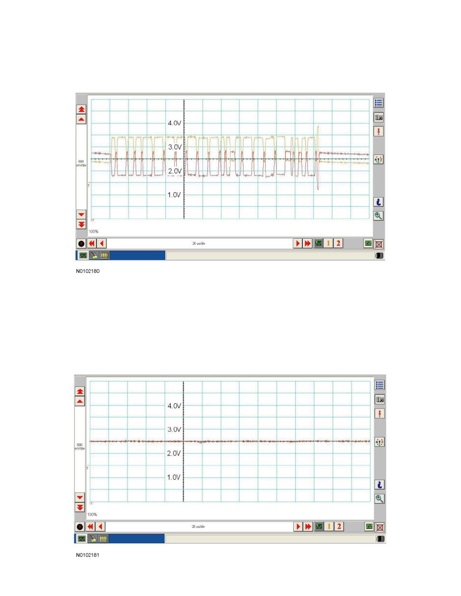
CAN Circuits Shorted Together
In the event that the data (+) and data (-) circuits become shorted together, the signal stays at base voltage (2.5V) continuously and all communication