
Milan FWD V6-3.0L (2010)
NOTE: Most faults are due to connector and/or wiring concerns. Carry out a thorough inspection and verification before proceeding with the pinpoint
test. See: Initial Inspection and Diagnostic Overview/Communications Network/Inspection and Verification
NOTE: Failure to disconnect the battery when instructed will result in false resistance readings. Refer to Battery.
-------------------------------------------------
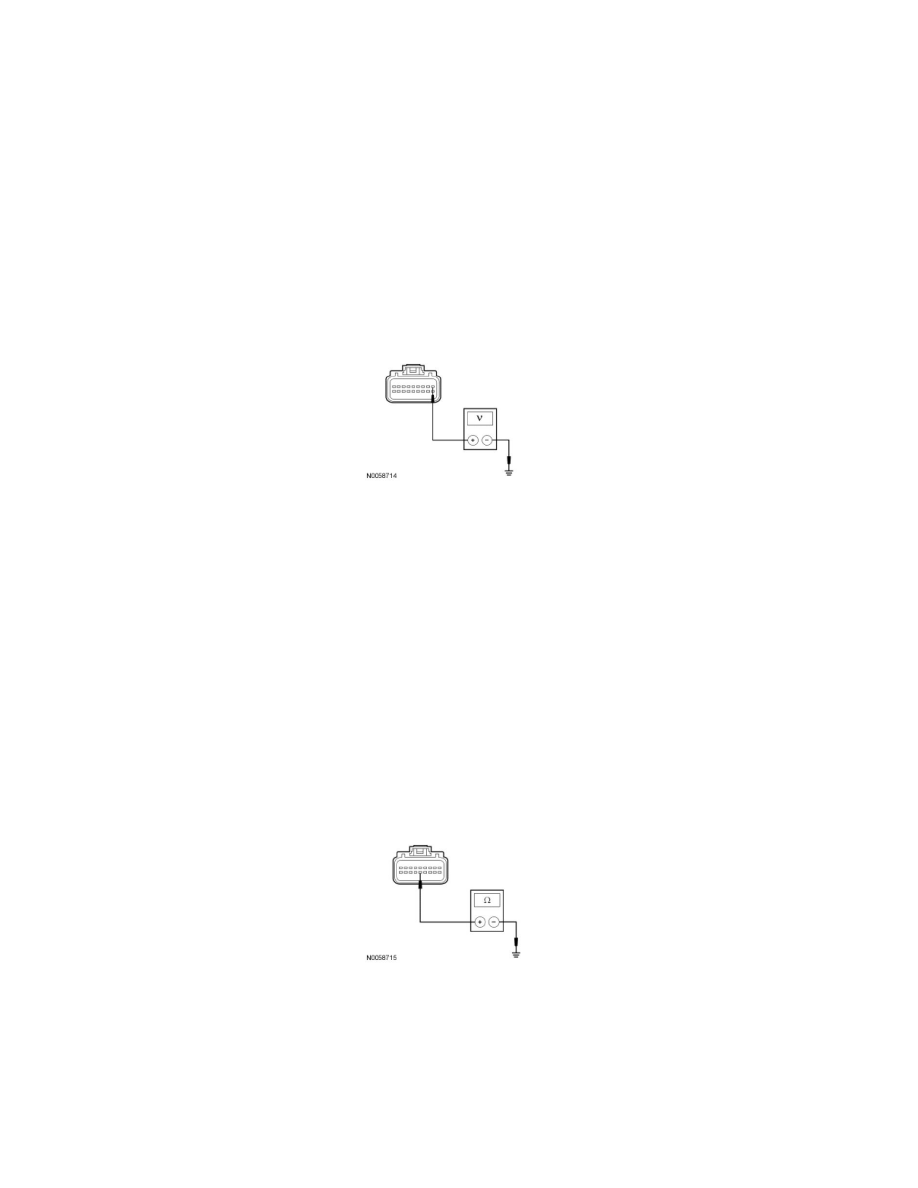
F1 CHECK THE OCSM VOLTAGE SUPPLY CIRCUIT FOR AN OPEN
-
Ignition OFF.
-
Depower the SRS. Refer to Restraint Systems.
-
Disconnect: OCSM C3159 .
-
Deactivate the SRS. Refer to Restraint Systems.
-
Repower the SRS. Refer to Restraint Systems.
-
Ignition ON.
-
Measure the voltage between the OCSM C3159-1, circuit CBP46 (WH/BU), harness side and ground.
-
Is the voltage greater than 10 volts?
Yes
GO to F2.
No
VERIFY the Smart Junction Box (SJB) fuse 46 (7.5A) is OK. If OK, REPAIR the circuit. REACTIVATE the SRS.
REFER to Restraint Systems. CLEAR the DTCs. REPEAT the network test with the scan tool.
-------------------------------------------------
F2 CHECK THE OCSM GROUND CIRCUIT FOR AN OPEN
-
Ignition OFF.
-
Disconnect: Negative Battery Cable .
-
Measure the resistance between the OCSM C3159-14, circuit GD127 (BK/BU), harness side and ground.
-
Is the resistance less than 5 ohms?
Yes
GO to F3.
No
REPAIR the circuit. REACTIVATE the SRS. CONNECT the negative battery cable. REFER to Restraint Systems. CLEAR the DTCs. REPEAT the
network test with the scan tool.