
Milan FWD V6-3.0L (2010)
Yes
GO to H3.
No
REPAIR the circuit. CLEAR the DTCs. REPEAT the network test with the scan tool.
-------------------------------------------------
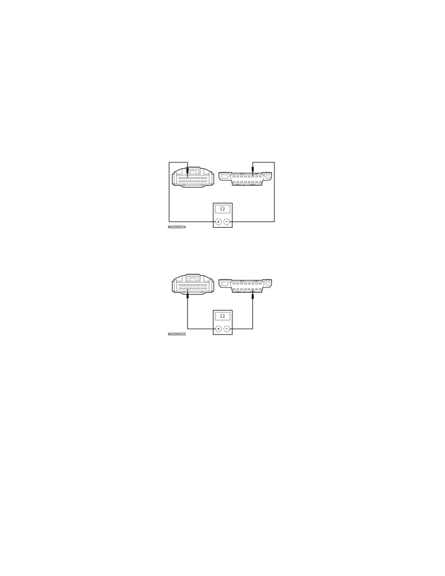
H3 CHECK THE HS-CAN CIRCUITS BETWEEN THE 4X4 CONTROL MODULE AND THE DLC FOR AN OPEN
-
Measure the resistance between the 4X4 control module C3253-3, circuit VDB04 (WH/BU), harness side and the Data Link Connector (DLC)
C251-6, circuit VDB04 (WH/BU), harness side.
-
Measure the resistance between the 4X4 control module C3253-11, circuit VDB05 (WH), harness side and the DLC C251-14, circuit VDB05
(WH), harness side.
-
Are the resistances less than 5 ohms?
Yes
CONNECT the negative battery cable. GO to H4.
No
REPAIR the circuit in question. CONNECT the negative battery cable. CLEAR the DTCs. REPEAT the network test with the scan tool.
-------------------------------------------------
H4 CHECK FOR CORRECT 4X4 CONTROL MODULE OPERATION
-
Disconnect the 4X4 control module connector.
-
Check for:
-
corrosion
-
damaged pins
-
pushed-out pins
-
Connect the 4X4 control module connector and make sure it seats correctly.
-
Operate the system and verify the concern is still present.
-
Is the concern still present?
Yes