
Milan FWD V6-3.0L (2010)
-
DDM
PINPOINT TEST X: THE DRIVER DOOR MODULE (DDM) DOES NOT RESPOND TO THE SCAN TOOL
NOTICE: Use the correct probe adapter(s) when making measurements. Failure to use the correct probe adapter(s) may damage the
connector.
NOTE: Failure to disconnect the battery when instructed will result in false resistance readings. Refer to Battery.
-------------------------------------------------
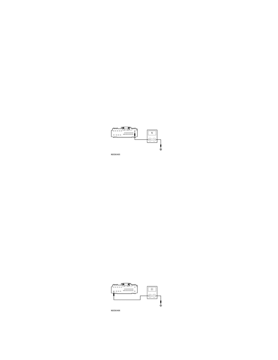
X1 CHECK THE DDM VOLTAGE SUPPLY CIRCUIT FOR AN OPEN
-
Ignition OFF.
-
Disconnect: DDM C568b .
-
Ignition ON.
-
Measure the voltage between the DDM C568b-1, circuit SBP12 (GN/RD), harness side and ground.
-
Is the voltage greater than 10 volts?
Yes
GO to X2.
No
VERIFY the Smart Junction Box (SJB) fuse 12 (7.5A) is OK. If OK, REPAIR the circuit. If not OK, REFER to the Wiring Diagrams to identify the
possible causes of the short circuit. See: Diagrams/Electrical Diagrams/Diagrams By Number
CLEAR the DTCs. REPEAT the network test with the scan tool.
-------------------------------------------------
X2 CHECK THE DDM GROUND CIRCUIT FOR AN OPEN
-
Ignition OFF.
-
Disconnect: Negative Battery Cable .
-
Measure the resistance between the DDM C568b-24, circuit GD126 (BK/WH), harness side and ground.
-
Is the resistance less than 5 ohms?
Yes
GO to X3.