
Milan FWD V6-3.0L (2010)
with the scan tool. If not OK, REFER to the Wiring Diagrams to identify the possible causes of the circuit short See: Diagrams/Electrical
Diagrams/Diagrams By Number.
-------------------------------------------------
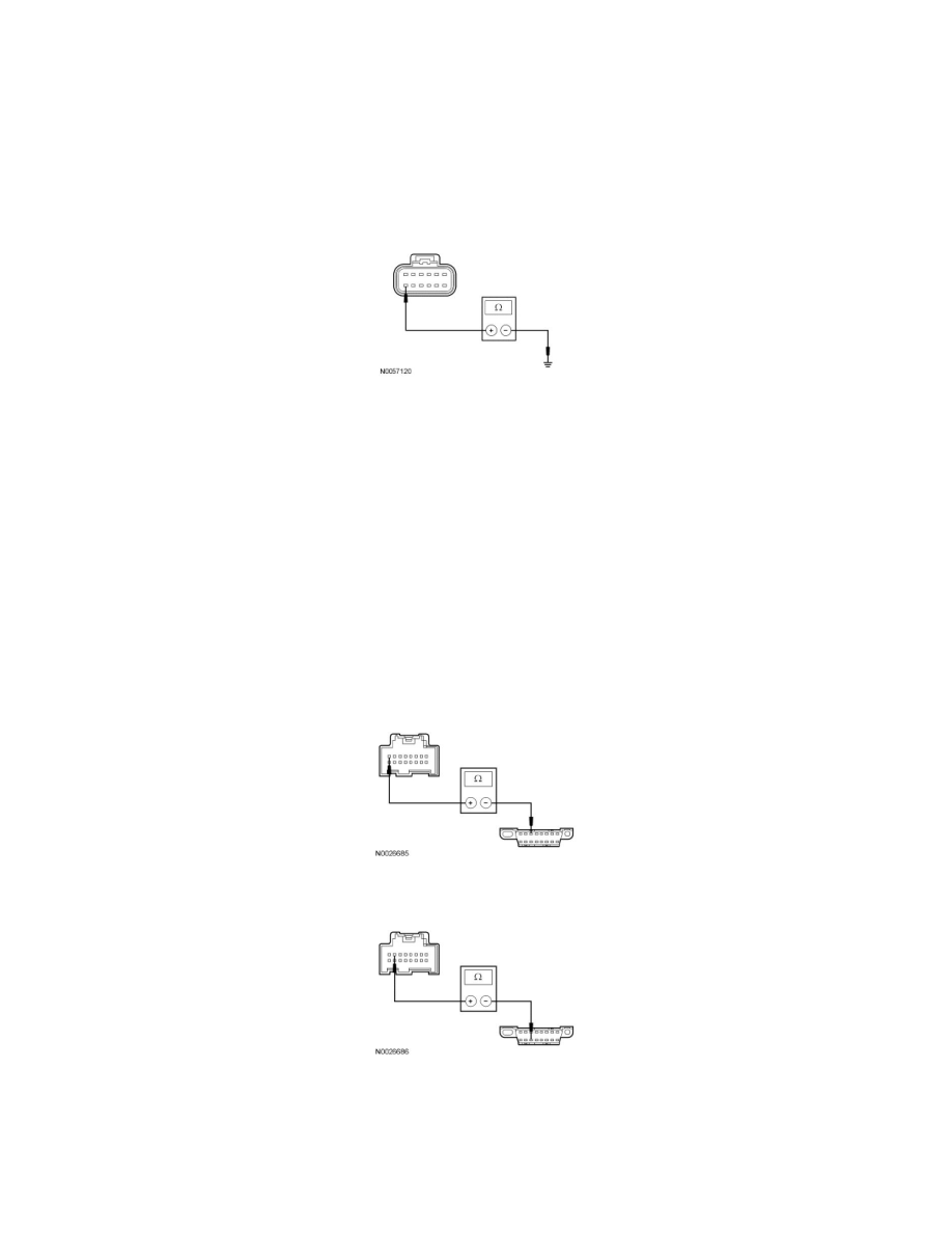
Y4 CHECK THE DCSM GROUND CIRCUIT FOR AN OPEN
-
Ignition OFF.
-
Disconnect: Negative Battery Cable .
-
Measure the resistance between the DCSM C3305a-M, circuit GD139 (BK/YE), harness side and ground.
-
Is the resistance less than 5 ohms?
Yes
GO to Y5.
No
REPAIR the circuit. CONNECT the negative battery cable. CLEAR the DTCs. REPEAT the network test with the scan tool.
-------------------------------------------------
Y5 CHECK THE MS-CAN CIRCUITS BETWEEN THE DCSM AND THE DLC FOR AN OPEN
-
Disconnect: DCSM C3305c .
-
Measure the resistance between the DCSM C3305c-1, circuit VDB06 (GY/OG), harness side and the Data Link Connector (DLC) C251-3, circuit
VDB06 (GY/OG), harness side.
-
Measure the resistance between the DCSM C3305c-2, circuit VDB07 (VT/OG), harness side and the DLC C251-11, circuit VDB07 (VT/OG),
harness side.
-
Are the resistances less than 5 ohms?
Yes
CONNECT the negative battery cable. GO to Y6.
No