
Milan FWD V6-3.0L (2010)
-
Accessory Protocol Interface Module (APIM) (if equipped)
-
Air Conditioning Compressor Module (ACCM) (Hybrid only)
-
Battery Energy Control Module (BECM) (Hybrid only)
-
DC/DC (Hybrid only)
-
Headlamp Control Module (HCM) (if equipped)
-
Instrument Panel Cluster (IPC)
-
Occupant Classification System Module (OCSM)
-
PCM
-
Power Steering Control Module (PSCM) (if equipped)
-
Restraints Control Module (RCM)
-
Transmission Control Module (TCM) (if equipped)
This pinpoint test is intended to diagnose the following:
-
Circuit VDB04 (WH/BU) (HS-CAN +) open
-
Circuit VDB05 (WH) (HS-CAN -) open
PINPOINT TEST AD: INTERMITTENT NO HS-CAN COMMUNICATION, ONE OR MORE MODULES ARE NOT RESPONDING
DURING NETWORK TEST
NOTE: Most faults are due to connector and/or wiring concerns. Carry out a thorough inspection and verification before proceeding with the pinpoint
test. See: Initial Inspection and Diagnostic Overview/Communications Network/Inspection and Verification
NOTE: Various network DTCs will set while disabling modules in this test procedure which will need to be cleared after the diagnostic procedure is
completed.
NOTE: Failure to disconnect the battery when instructed will result in false resistance readings. Refer to Battery.
-------------------------------------------------
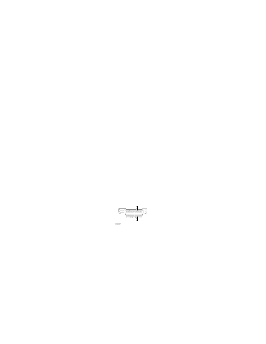
AD1 CHECK THE DLC PINS FOR DAMAGE
-
Ignition OFF.
-
Disconnect the scan tool cable from the DLC.
-
Inspect DLC pins 6 and 14 for damage.
-
Are DLC pins 6 and 14 OK?
Yes
GO to AD2.
No
REPAIR the DLC as necessary. CLEAR the DTCs. REPEAT the network test with the scan tool.
-------------------------------------------------
AD2 CHECK THE HS-CAN TERMINATION RESISTANCE
-
Ignition OFF.
-
Disconnect: Negative Battery Cable .
-
Measure the resistance between the DLC C251-6, circuit VDB04 (WH/BU), harness side and the DLC C251-14, circuit VDB05 (WH), harness
side.