
Milan FWD V6-3.0L (2010)
-------------------------------------------------
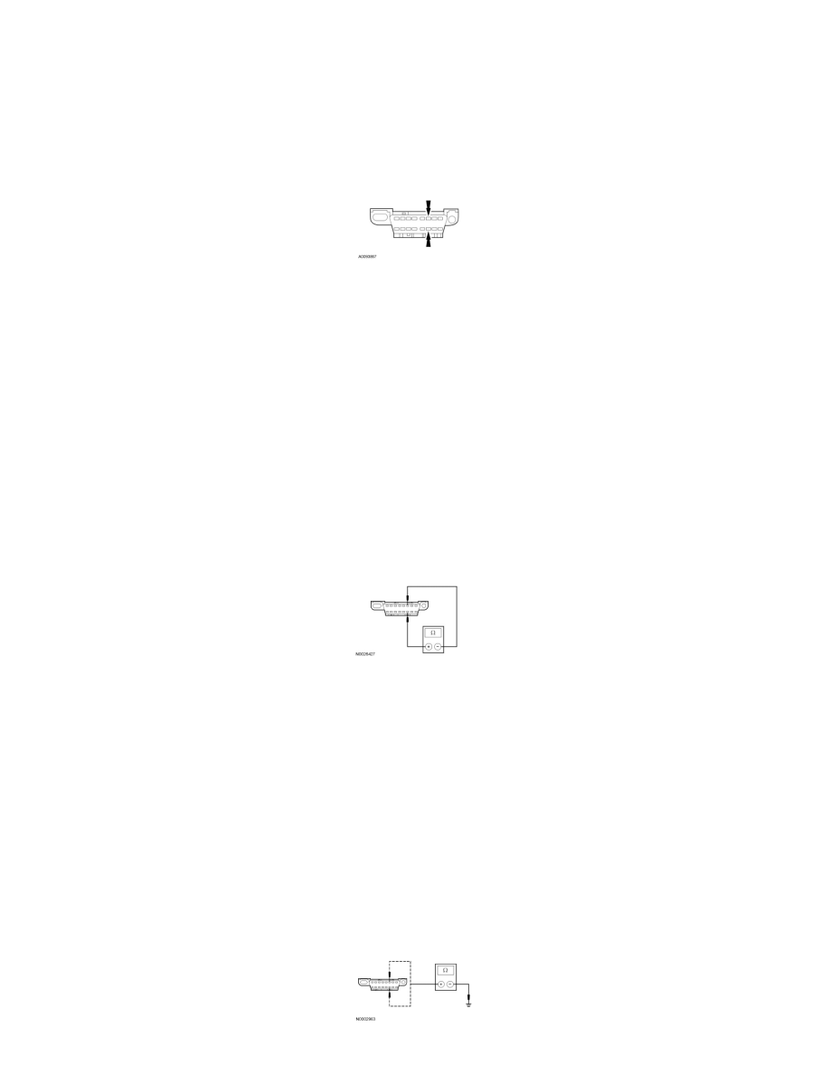
AE1 CHECK THE DLC PINS FOR DAMAGE
-
Ignition OFF.
-
Disconnect the scan tool cable from the Data Link Connector (DLC).
-
Inspect DLC pins 6 and 14 for damage.
-
Are DLC pins 6 and 14 OK?
Yes
GO to AE2.
No
REPAIR the DLC as necessary. CLEAR the DTCs. REPEAT the network test with the scan tool.
-------------------------------------------------
AE2 CHECK THE HS-CAN TERMINATION RESISTANCE
-
Ignition OFF.
-
Disconnect: Negative Battery Cable .
-
Measure the resistance between the DLC C251-6, circuit VDB04 (WH/BU), harness side and the DLC C251-14, circuit VDB05 (WH), harness
side.
-
Is the resistance between 54 and 66 ohms?
Yes
GO to AE3.
No
GO to AE5.
-------------------------------------------------
AE3 CHECK THE HS-CAN (+) AND HS-CAN (-) CIRCUITS FOR A SHORT TO GROUND
-
Measure the resistance between the DLC C251-6, circuit VDB04 (WH/BU), harness side and ground; and between the DLC C251-14, circuit
VDB05 (WH), harness side and ground.