
Milan FWD V6-3.0L (2010)
1. Tighten to 24 Nm (18 lb-ft)
2. Stud bolt location
63. Remove the Turbine Shaft Seal Protector 307-635.
64. Install the Output Shaft Speed (OSS) sensor and the bolt.
Tighten to 10 Nm (89 lb-in).
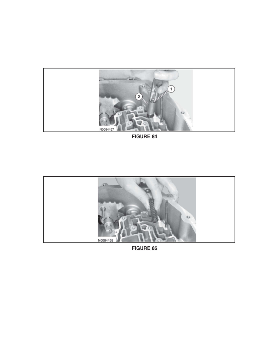
65. Assemble the internal cooler bypass valve in the sleeve and install the assembly in the case. See Figure 84.
1. Bypass valve.
2. Bypass valve sleeve
66. Install the internal cooler bypass valve spring. See Figure 85.
67. Install the new main control-to-transaxle separator plate and align it on the stud and the guide pin.
68. NOTE: Be sure that the manual pin (part of the TR sensor) is correctly installed in the manual valve.