
Milan FWD V6-3.0L (2010)
normal operation.
-------------------------------------------------
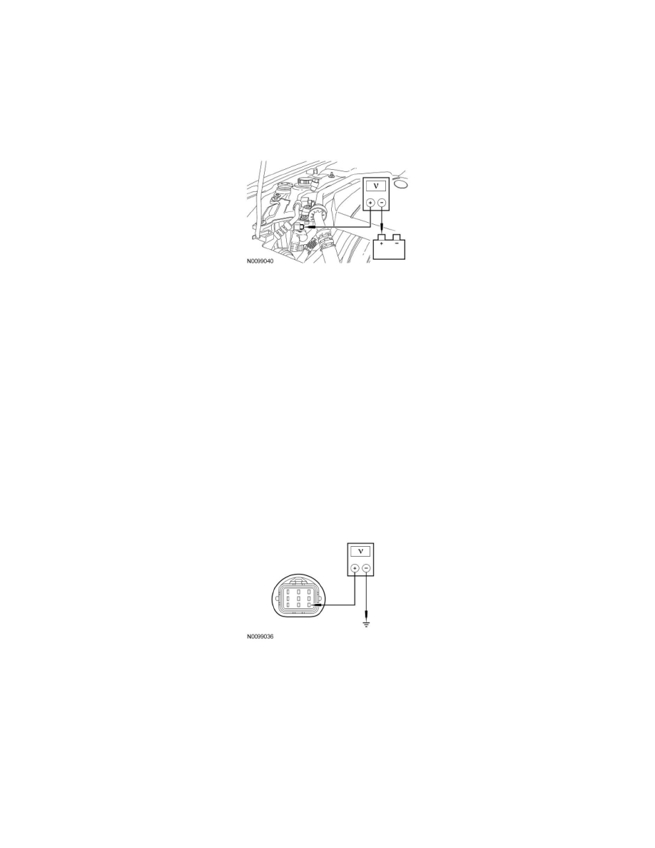
J3 MEASURE VOLTAGE DROP OF DC/DC B+ CIRCUIT
-
Ignition ON.
-
With the headlamps ON and the blower on high, measure the voltage between DC/DC C1457B, circuit SDC02 (RD), harness side and the positive
battery terminal.
-
Is the voltage drop less 0.5 volt?
Yes
GO to J4.
No
REPAIR DC/DC B+ circuit SDC02 (RD) or INSTALL a new cable, if necessary. CLEAR the DTC. REPEAT the self-test. TEST the system for normal
operation.
-------------------------------------------------
J4 CHECK THE PCM RELAY CONTROL INPUT TO THE DC/DC
-
Ignition OFF.
-
Disconnect: DC/DC C1457D.
-
Ignition ON.
-
Measure the voltage between DC/DC C1457D-7, circuit CBK03 (GY), harness side and ground.
-
Is the voltage greater than 10 volts?
Yes
GO to J5.
No
VERIFY the Battery Junction Box (BJB) fuse 47 (10A) is OK. If OK, REPAIR circuit CBK03 (GY). If not OK, REFER to the Wiring Diagrams to
identify the possible causes of the circuit short See: Diagrams/Electrical Diagrams/Diagrams By Number.
CLEAR the DTC. REPEAT the self-test. TEST the system for normal operation.
-------------------------------------------------