
Milan FWD V6-3.0L (2010)
-
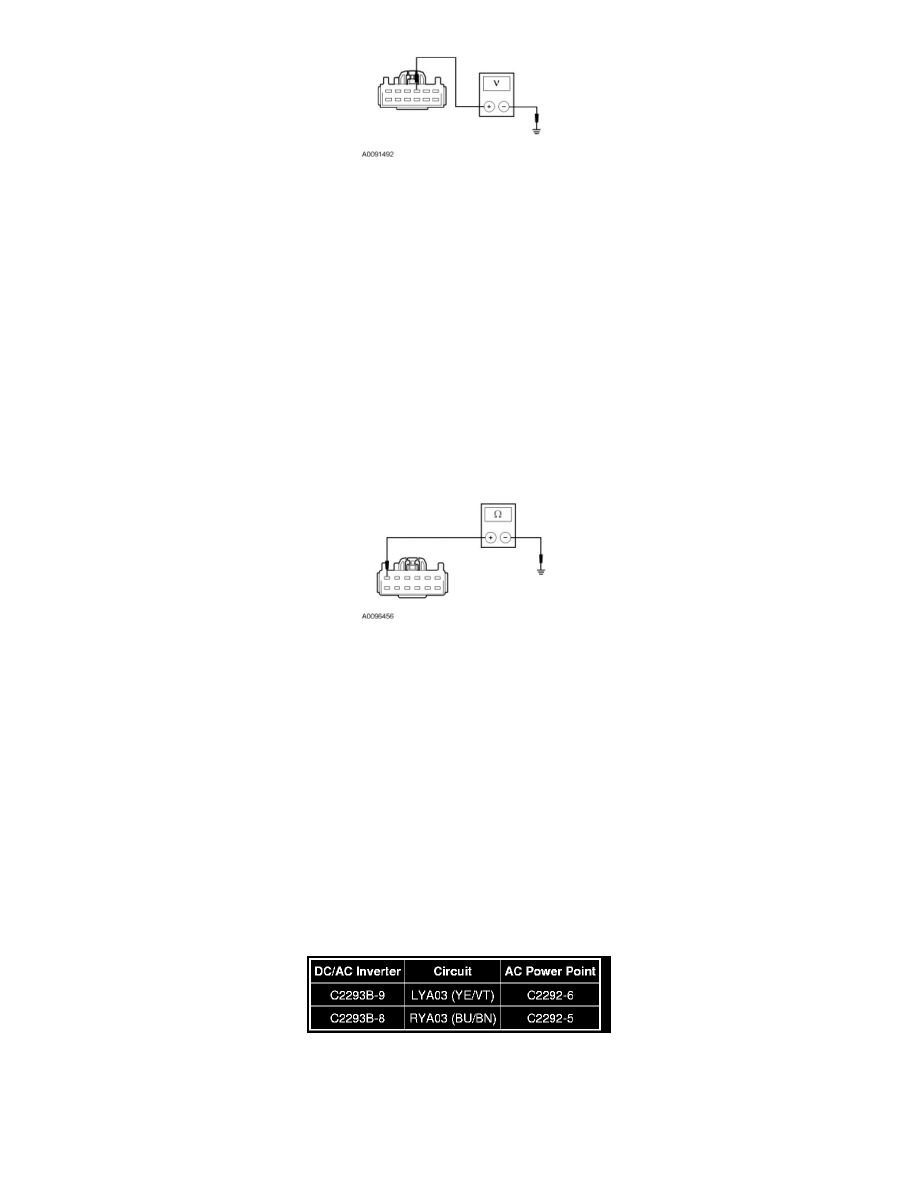
Is the voltage greater than 10 volts?
Yes
GO to L2.
No
VERIFY Smart Junction Box (SJB) fuse 35 (10A). If OK, REPAIR circuit CBP35 (YE/GY). If not OK, REFER to the Wiring Diagrams to identify the
possible causes of the circuit short See: Diagrams/Electrical Diagrams/Diagrams By Number. TEST the system for normal operation.
-------------------------------------------------
L2 CHECK DC/AC INVERTER GROUND CIRCUIT
-
Ignition OFF.
-
Measure the resistance between DC/AC inverter C2293A-6, circuit GD139 (BK/YE), harness side and ground.
-
Is the resistance less than 5 ohms?
Yes
GO to L3.
No
REPAIR circuit GD139 (BK/YE). TEST the system for normal operation.
-------------------------------------------------
L3 CHECK AC POWER POINT LED INDICATOR CIRCUITS FOR AN OPEN
-
Disconnect: DC/AC Inverter C2293B.
-
Disconnect: AC Power Point C2292.
-
Measure the resistance between DC/AC inverter C2293B, harness side and AC power point C2292 as follows: