
Milan FWD V6-3.0L (2010)
-
Discard the bolt.
-
To install, tighten the new bolt to 110 Nm (81 lb-ft), then tighten an additional 90 degrees with the suspension at the bushing fastener
tightening position.
4. Remove the damper fork-to-lower arm bolt flagnut and damper.
-
Discard the bolt and flagnut.
-
To install, tighten the new bolt and flagnut to 103 Nm (76 lb-ft) with the suspension at the bushing fastener tightening position.
5. Remove and discard the front lower ball joint nut.
-
To install, tighten the new nut to 200 Nm (148 lb-ft).
6. NOTICE: When the lower ball joint is separated from the wheel knuckle, the lower arm may strike the outer Constant Velocity (CV)
joint boot with enough force to damage the boot clamp. This will result in a loss of grease from the outer CV joint. Place a block of wood,
or similar item, between the lower arm and the outer CV joint to prevent the lower arm from striking the outer CV joint.
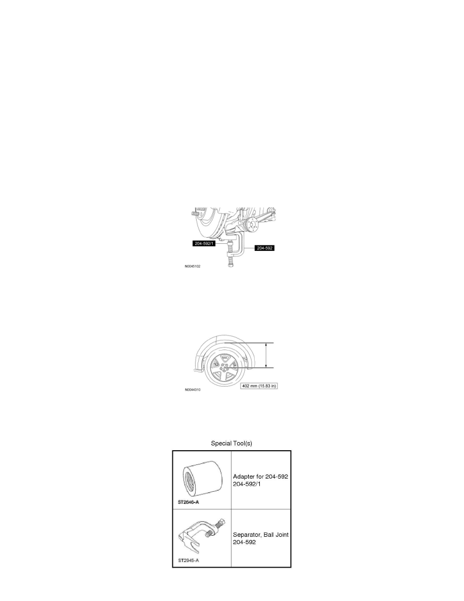
NOTE: Once pressure is applied to the ball joint with the Ball Joint Separator and Adapter, it may be necessary to tap the wheel knuckle at the
ball joint area to separate the ball joint from the wheel knuckle.
Using the Ball Joint Separator and Adapter, separate the front lower ball joint from the wheel knuckle and remove the front lower arm.
7. NOTICE: Before tightening any suspension bushing fasteners, the suspension must be at the bushing fastener tightening position. Use a
suitable jack to raise the suspension until the distance between the center of the hub and the lip of the fender is equal to 402 mm (15.83
in). This will prevent incorrect clamp load and bushing damage.
To install, reverse the removal procedure.
Lower Arm - Rear
Lower Arm - Rear