
Milan FWD V6-3.0L (2010)
4. Remove the wheel speed sensor harness bolt and position the wheel speed sensor aside.
-
To install, tighten to 23 Nm (17 lb-ft).
5. Using a suitable jack, support the wheel knuckle at the lower ball joints.
6. NOTE: Use the hex-holding feature to prevent the ball stud from turning while removing or installing the stabilizer bar link nut.
Remove and discard the stabilizer bar link upper nut.
-
To install, tighten the new nut to 42 Nm (31 lb-ft).
7. Remove the damper fork-to-front lower arm bolt, flagnut and damper.
-
Discard the bolt and flagnut.
-
To install, tighten the new bolt and flagnut to 103 Nm (76 lb-ft) with the suspension at the bushing fastener tightening position.
8. Remove and discard the shock absorber-to-damper fork bolt and separate the damper fork from the shock absorber and spring assembly.
-
To install, tighten the new bolt to 48 Nm (35 lb-ft).
9. Lower the wheel knuckle and remove the shock absorber and spring assembly.
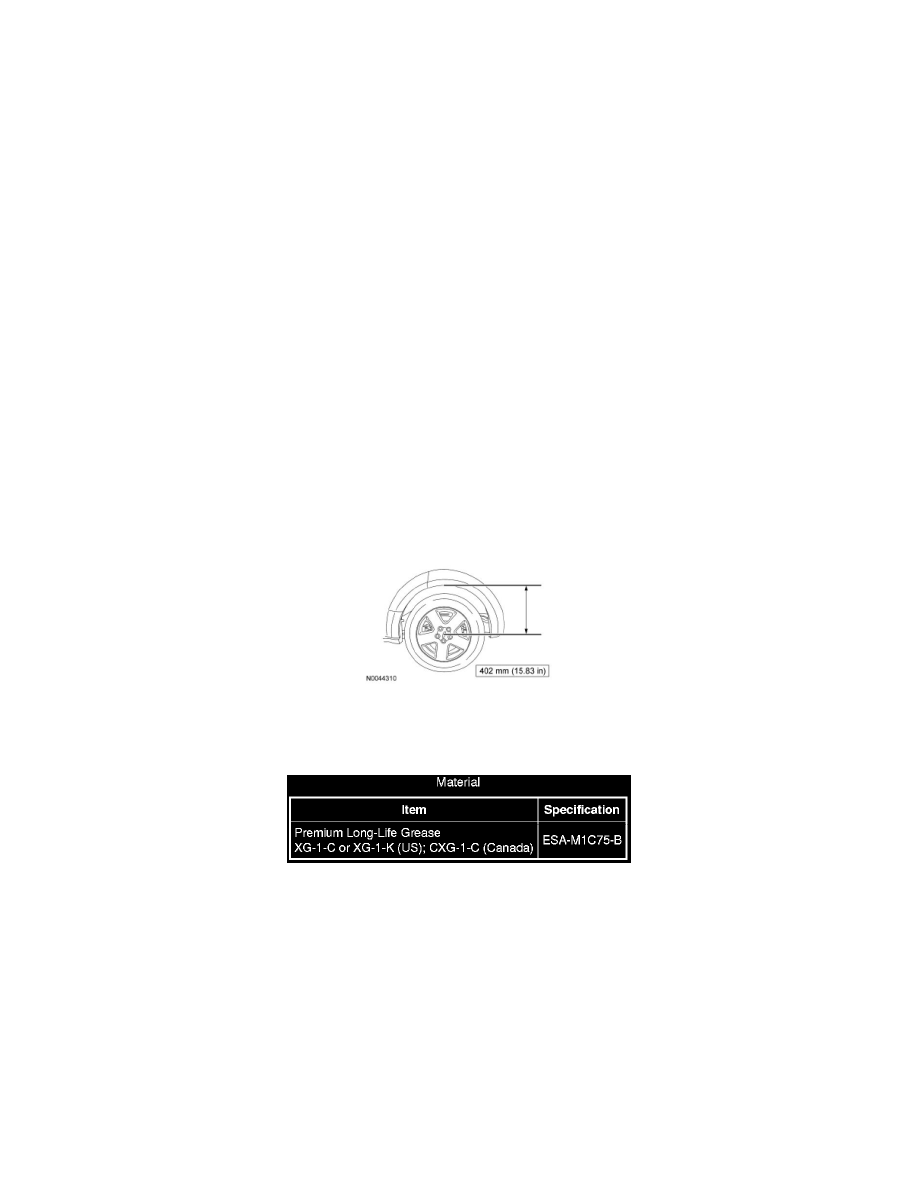
10. NOTICE: Before tightening any suspension bushing fasteners, the suspension must be at the bushing fastener tightening position. Use a
suitable jack to raise the suspension until the distance between the center of the hub and the lip of the fender is equal to 402 mm (15.83
in). This will prevent incorrect clamp load and bushing damage.
To install, reverse the removal procedure.
11. For additional information on the disassembly and assembly of the shock absorber and spring assembly, refer to Shock Absorber and Spring
Assembly See: Suspension Strut / Shock Absorber/Service and Repair/Overhaul.
Rear Suspension - Spring
Spring
NOTE: Front Wheel Drive (FWD) shown, AWD similar.