
Repair Shift Solenoid in Milan FWD V6-30L (2010) Automatic Transmissions
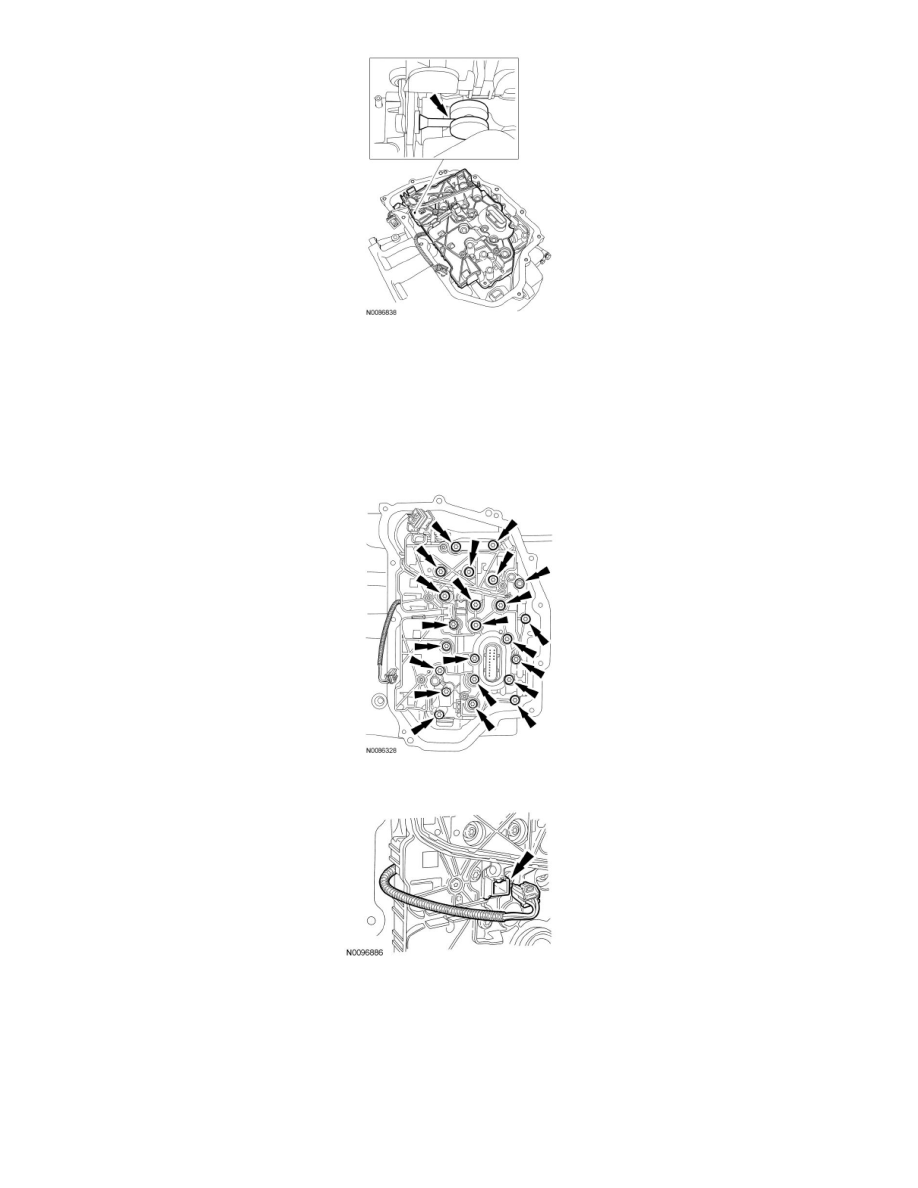
4. NOTICE: Make sure not to pinch the Output Shaft Speed (OSS) or Transmission Range (TR) sensor wiring harnesses when installing the
main control.
NOTE: Install the different length bolts in the locations noted during disassembly.
Install the main control stud nut and 22 main control valve body bolts. Tighten in a crisscross pattern.
-
Tighten to 10 Nm (89 lb-in).
5. Route the OSS sensor wiring harness and connect the electrical connector.
6. Connect the TR sensor electrical connector.