
Milan FWD V6-3.0L (2010)
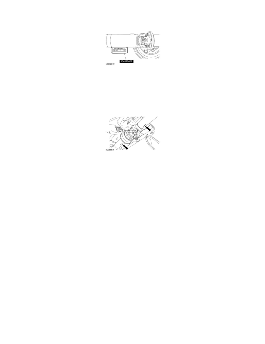
3. Using the Anglemaster II Driveline Inclinometer/Protractor, measure the slope of the connecting component. Record the measurement of the
component angle as angle B.
Multiple piece driveshafts
4. NOTE: Repeat this step for each center support bearing on the driveshaft.
NOTE: It is not necessary to remove the U-joint snap ring, if equipped, for these measurements.
Using the Anglemaster II Driveline Inclinometer/Protractor, measure the slope of the components in front and behind the center support bearing
U-joint in the area indicated. Record the front component as angle A and the rear component as angle B.
All vehicles
5. NOTE: When 2 connected components slope in the same direction, subtract the smallest number from the larger number to find the U-joint
operating angle. When 2 connected components slope in the opposite direction, add the measurements to find the U-joint operating angle.
Calculate the difference in the slope of the components to determine the U-joint operating angle.
-
The U-joint operating angle is the angle formed by 2 yokes connected by a cross and bearing kit. Ideally, the operating angles on each
connection of the driveshaft must:
-
be equal or within one degree of each other.
-
have a 3 degree maximum operating angle.
-
have at least one-half of one degree continuous operating angle.
6. If the angle is not within specifications, repair or adjust to obtain the correct angle. Inspect the engine mounts, transmission mounts, center support
bearing mounting, rear suspension, rear axle, rear axle mounting or the frame for wear or damage.
Driveshaft Runout and Balancing
Driveshaft Runout and Balancing