
Montego AWD V6-3.0L VIN 1 (2005)
Part 2
Removal and Installation
All vehicles
1. Remove the rear wheels.
2. With a wax pencil, mark the relational alignment of the rear subframe to the underbody at the mounting locations.
3. Remove the muffler and tailpipe assembly.
4. NOTE:
-
Index the driveshaft before disconnecting from the rear drive axle.
-
It is necessary to install new driveshaft bolts during installation. Reuse of the driveshaft bolts is not recommended.
Remove the 6 driveshaft bolts.
-
To install, tighten to 25 Nm (18 lb-ft).
5. Loosen the trailing link-to-subframe bolts.
-
To install, tighten to 105 Nm (77 lb-ft).
6. Support and raise the knuckle with a suitable jack.
-
Raise the knuckle until the tilt angle of the trailing link is horizontal to the body.
7. Remove the trailing link-to-knuckle bolts.
-
To install, tighten to 105 Nm (77 lb-ft).
8. Position the trailing link aside.
9. Remove the rear shock-to-lower control arm bolts.
-
To install, tighten the rear shock-to-lower control arm bolts - AWD to 142 Nm (105 lb-ft).
-
To install, tighten the rear shock-to-lower control arm bolts - FWD to 110 Nm (81 lb-ft).
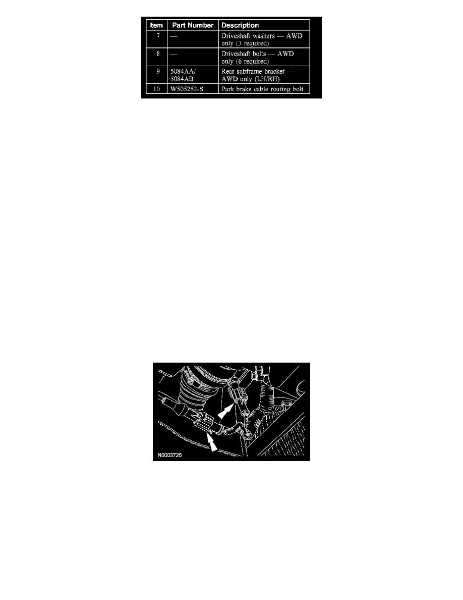
10. Disconnect the rear wheel speed sensor electrical connectors.
AWD vehicles