
Montego AWD V6-3.0L VIN 1 (2005)
Part 2
Removal and Installation
CAUTION: It is necessary to cut the underbody auxiliary line(s) being serviced into sections to facilitate removal. Make sure to correctly
identify the line(s) being serviced before carrying out any cutting of the line(s).
NOTE:
-
The auxiliary heater inlet and outlet lines are not supplied together as an assembly. The auxiliary heater inlet line and outlet line are each installed
from the factory as one-piece assemblies. The replacement parts are supplied as separate kits containing 2-piece lines for ease of installation.
-
The following procedure can be used to remove and install one, or both of the auxiliary heater inlet line and auxiliary heater outlet lines. If only
one auxiliary heater line is to be removed and installed, cut or disconnect only the desired line at the specified points within the procedure.
All vehicles
1. Drain the engine coolant.
2. Remove the muffler.
AWD vehicles
3. Remove the rear driveshaft.
All vehicles
4. Remove the exhaust heat shield.
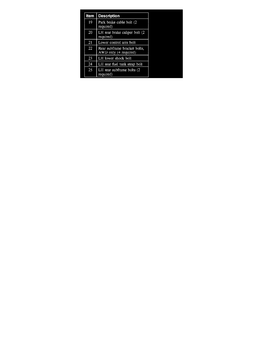
5. Remove the front auxiliary heater outlet line clamp and disconnect the line.
6. Remove the front auxiliary heater inlet line clamp and disconnect the line.
7. Remove the LH rear wheel.
8. Remove the LH rear quarter panel moulding.
9. Remove the 3 outer LH rear quarter panel moulding bracket bolts and the LH rear quarter panel moulding bracket.
10. Remove the 2 inner LH rear quarter panel moulding bracket bolts and the LH rear quarter panel moulding bracket.
11. Remove the LH rear quarter panel moulding bracket.
12. Remove the 2 LH rear brake caliper bolts and position the caliper aside.
-
To install, tighten to 35 Nm (26 lb-ft).
13. Remove the 2 parking brake cable bolts.
-
To install, tighten to 12 Nm (9 lb-ft).
AWD vehicles
14. Remove the 4 rear subframe bracket bolts.
-
To install, tighten to 63 Nm (46 lb-ft).
15. Remove the lower control arm bolt.
-
To install, tighten to 90 Nm (66 lb-ft).
All vehicles
16. Remove the LH lower shock bolt.
-
To install, tighten to 142 Nm (105 lb-ft).
17. Position a lifting table to support the rear subframe.
18. Remove the 2 LH rear subframe bolts and lower the subframe.
-
To install, tighten to 115 Nm (85 lb-ft).