
Montego AWD V6-3.0L VIN 1 (2005)
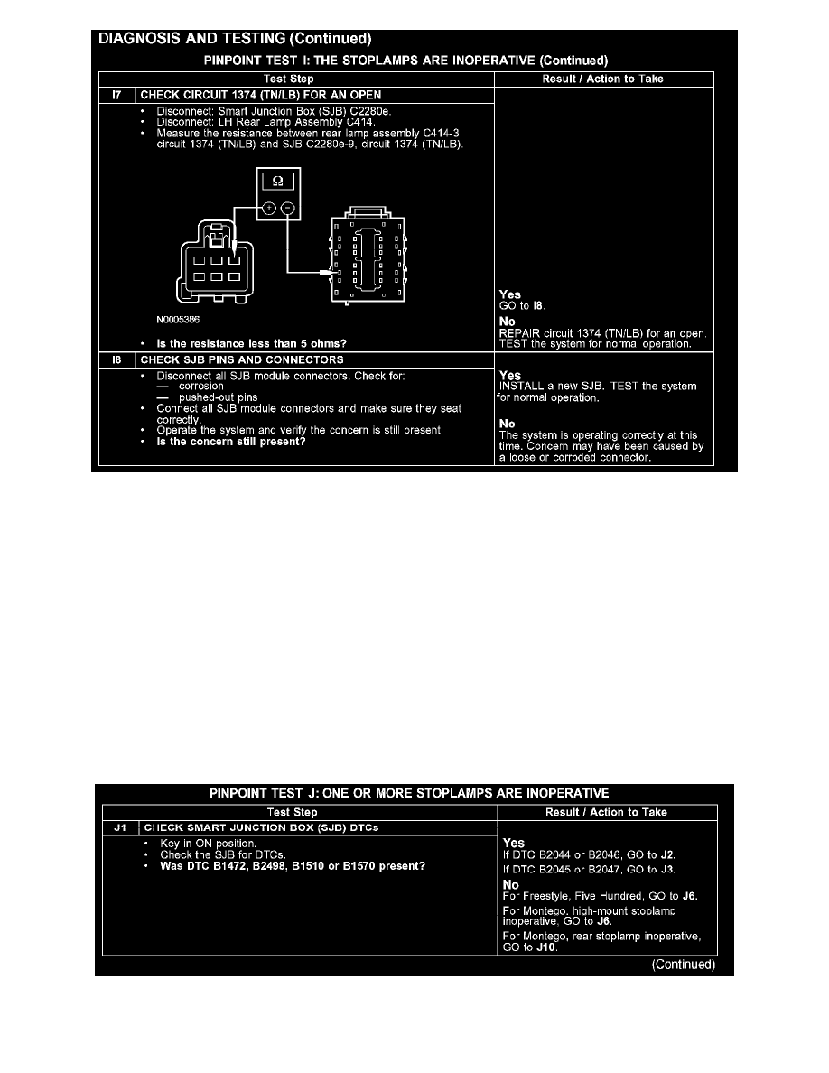
I7-I8
Normal Operation
Under normal operation, when the brake pedal is applied, the stoplamp switch sends a voltage signal to the smart junction box (SJB) through circuit
810 (RD/LG). Voltage for the switch is provided by circuit 1140 (VT). The SJB then sends voltage to the high mounted stoplamps through circuit
1374 (TN/LB).
The SJB then sends a voltage to the rear stoplamps through:
-
Freestyle, Five Hundred: (LH) circuit 1363 (WH/RD) and (RH) circuit 1365 (GY/LB).
-
Montego: circuit 1374 (TN/LB).
Possible Causes
-
An open in circuit 810 (RD/LG), 1374 (TN/LB) or 1140 (VT)
-
A short to ground in circuit 810 (RD/LG)
-
Stoplamp switch
-
Smart junction box (SJB)
Test J: One Or More Stoplamps Are Inoperative
PINPOINT TEST J: ONE OR MORE STOPLAMPS ARE INOPERATIVE
J1