
Montego AWD V6-3.0L VIN 1 (2005)
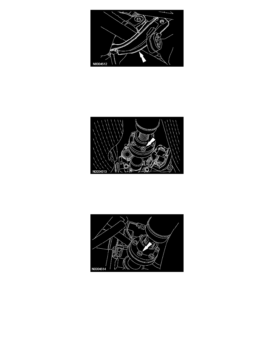
3. Remove the exhaust support brace bolts, then the exhaust support brace.
^
To install, tighten to 30 Nm (22 ft. lbs.).
4. WARNING: Failure to correctly index-mark the driveshaft will lead to noise, vibration or harshness (NVH) problems.
NOTE: Index-mark the driveshaft to the rear axle pinion flange, the power take off (PTO) flange and the center bearing bracket.
Index-mark the driveshaft.
5. WARNING: Always install new driveshaft flange bolts when removed.
NOTE: Use a cross pattern to tighten the driveshaft flange bolts.
Remove and discard the driveshaft flange bolts from the rear axle pinion flange, then disconnect the driveshaft from the rear axle pinion flange.
^
To install, tighten to 25 Nm (18 ft. lbs.).
6. WARNING: Always install new driveshaft flange bolts when removed.
NOTE: Use a cross pattern to tighten the driveshaft flange bolts.
Remove and discard the driveshaft flange bolts from the PTO flange, then disconnect the driveshaft from the PTO flange.
^
To install, tighten to 25 Nm (18 ft. lbs.).