
Monterey V6-4.2L VIN 2 (2004)
Test F6
Normal Operation
The stoplamp switch is supplied voltage from the SJB through circuit 10 (LG/RD). When the brake pedal is applied, the stoplamp switch routes
voltage to circuit 810 (LG/RD) back to the SJB. Circuit 810 (LG/RD) is then routed out of the SJB to the brake shift interlock solenoid.The SJB
monitors voltage input from the stoplamp switch. When the SJB senses brake pedal application, the SJB the sends voltage to the stoplamps.
Possible Causes
-
circuit 10 (LG/RD) open
-
circuit 810 (LG/RD) open
-
stoplamp switch
-
SJB
Test G
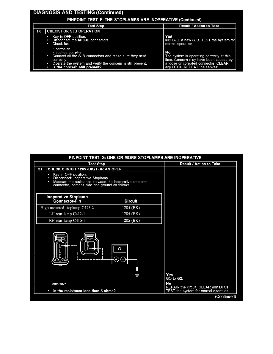
PINPOINT TEST G: ONE OR MORE STOPLAMPS ARE INOPERATIVE
Test G1