
Monterey V6-4.2L VIN 2 (2004)
Test H5-H7
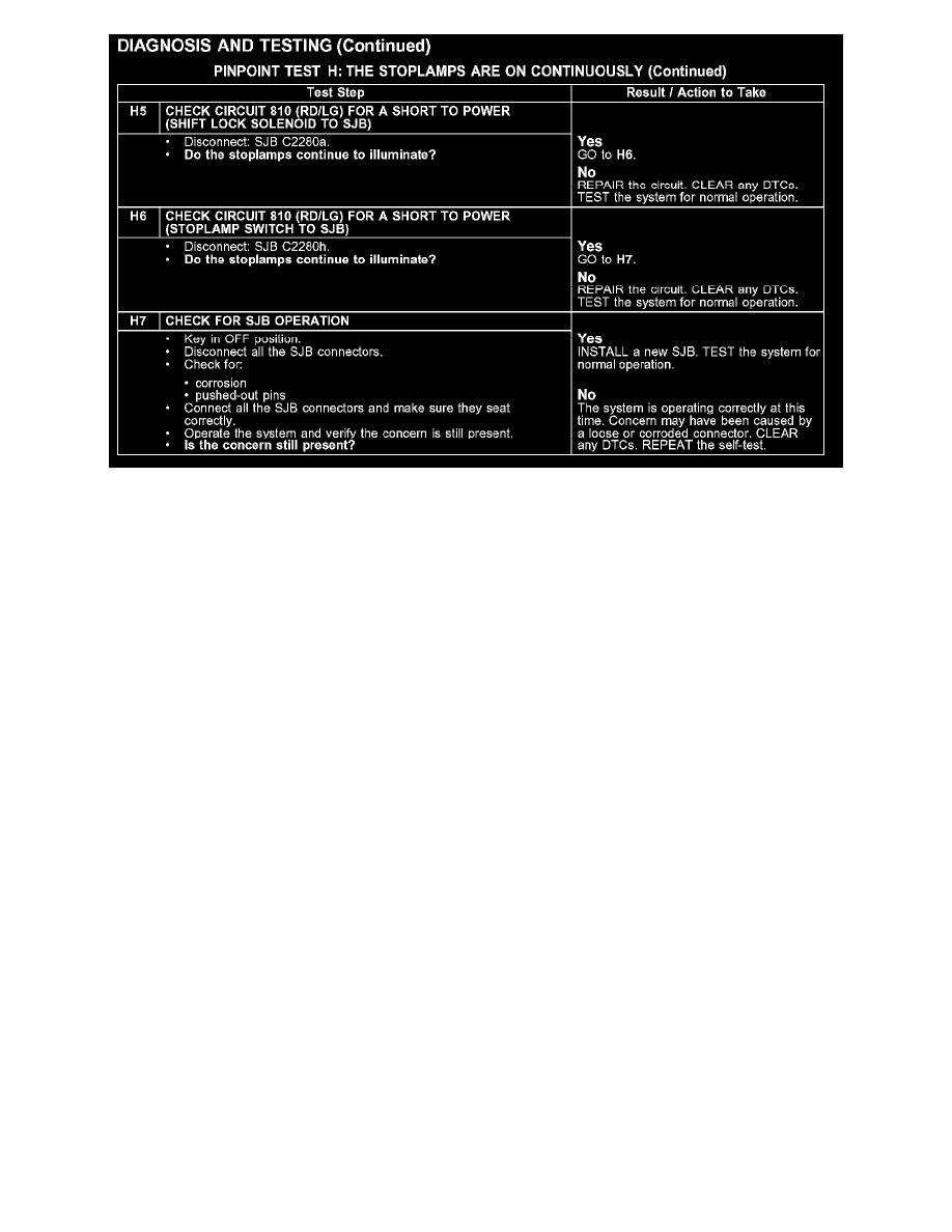
Normal Operation
The stoplamp switch is supplied voltage from the SJB through circuit 10 (LG/RD). When the brake pedal is applied, the stoplamp switch routes
voltage to circuit 810 (LG/RD) back to the SJB. Circuit 810 (LG/RD) is then routed out of the SJB to the brake shift interlock solenoid.The SJB
monitors voltage input from the stoplamp switch. When the SJB senses brake pedal application, the SJB then sends voltage to the rear lamps. Voltage
for the LH and RH stoplamps is supplied through circuits 1363 (WH/RD) and 1365 (GY/LB) respectively. Voltage for the high mounted stoplamp is
supplied through circuit 1456 (RD/LB). Ground for the stoplamps is provided through circuit 1205 (BK).
Possible Causes
-
circuit 810 (LG/RD) short to power
-
circuit 1363 (WH/RD) short to power
-
circuit 1365 (GY/LB) short to power
-
circuit 1456 (RD/LB) short to power
-
stoplamp switch
-
brake shift interlock solenoid
-
SJB