
Monterey V6-4.2L VIN 2 (2004)
8. Remove the restraint system diagnostic tool from the clockspring electrical connector at the top of the steering column.
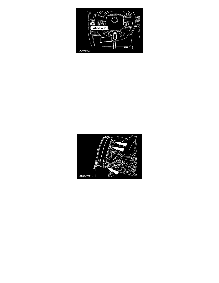
9. Through the steering wheel access door, connect the driver air bag module electrical connector.
-
Close the steering wheel access door.
10. WARNING: To reduce the risk of serious personal injury, read and follow all warnings, cautions, notes, and instructions in the
supplemental restraint system (SRS) deactivation/reactivation procedure. Refer to Air Bag(s) Arming and Disarming.
Reactivate the supplemental restraint system (SRS). Refer to Air Bag(s) Arming and Disarming.
11. Connect the battery ground cable.
12. WARNING: The restraint system diagnostic tool is for restraint system service only. Remove from the vehicle prior to road use. Failure
to remove could result in injury and possible violation of vehicle safety standards.
With all the restraint system diagnostic tools removed, prove out the supplemental restraint system (SRS). See: Air Bag(s) Arming and
Disarming/Service and Repair/Prove Out Procedure
Item 1: Clockspring Installation Note
1. CAUTION: Make sure the road wheels are in the straight-ahead position and the clockspring is centered before installing the
clockspring.
NOTE: Slight turning of the clockspring rotor is allowable for alignment purposes to the steering column.
Align the clockspring to the steering column and slide it down into place. Make sure the three clockspring retainers are securely snapped in place
on steering column.
Item 2: Connector Installation Note