
Monterey V6-4.2L VIN 2 (2004)
Constant Velocity Joint: All Technical Service Bulletins
Drivetrain - Outer CV Joint(s) Broken
TSB 05-9-8
05/16/05
OUTER CV JOINT BROKEN - VEHICLES BUILT
BEFORE 5/1/2005
FORD:
2004-2005 Freestar
MERCURY:
2004-2005 Monterey
ISSUE
Some 2004-2005 Freestar/Monterey vehicles built before 5/1/2005, may exhibit a broken outer C/V joint. This may occur when the vehicle steering is
turned hard in one direction and the vehicle is accelerated at a high rate.
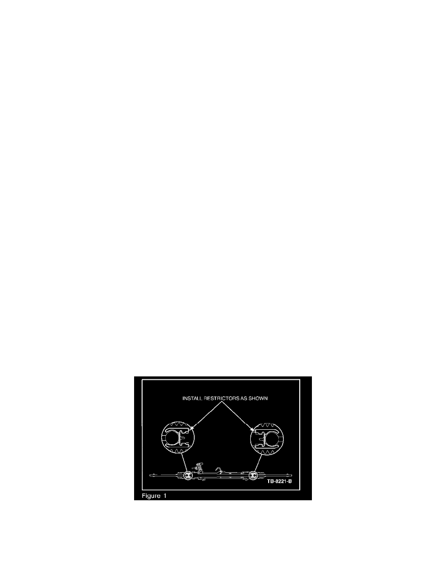
ACTION
Replace the outer C/V joint and install restrictors between the inner tie-rod ends and the steering rack. Refer to the following Service Procedure.
SERVICE PROCEDURE
1.
Replace the halfshaft (right and/or left). Refer to Section 205-04 of the Workshop Manual.
2.
Remove the steering gear. Refer to Section 211-00 of the Workshop Manual. If present, note the orientation of the steering gear vent tube. During
reinstallation the bellows and vent tube must be installed in the correct orientation.
NOTE
THE BELLOWS AND CLAMPS ON THE STEERING GEAR ARE DESIGNED TO PROVIDE AN AIRTIGHT SEAL TO PROTECT THE
INTERNAL COMPONENTS. IF THE BELLOWS SEAL IS NOT AIRTIGHT THE VACUUM GENERATED DURING TURNING WILL
DRAW WATER AND CONTAMINATION INTO THE GEAR CAUSING PREMATURE WEAR. ZIP TIES DO NOT PRODUCE AN
AIRTIGHT SEAL AND MUST NOT BE USED IN PLACE OF THE BELLOWS CLAMPS.
3.
Drain any excess power steering fluid from the steering gear and clean the exterior of the gear using a suitable solvent.
4.
Remove and discard the two (2) inner bellows clamps. New clamps must be installed.
5.
Slide the two (2) steering gear bellows aside to allow access to the inner tie-rods.
6.
Thoroughly clean any abrasive material from the inside of the bellows area. Thoroughly clean and inspect all the parts being reused.
7.
Install the restrictors on each side of the rack between the inner tie-rod and the steering gear housing (Figure 1).
8.
Position two (2) new inner bellows clamps onto the steering gear. DO NOT secure the inner bellows clamps at this point.
9.
Install the two (2) steering gear bellows over the steering gear.