
Mountaineer 2WD V6-245 4.0L VIN X SFI (2000)
Horn Relay: Testing and Inspection
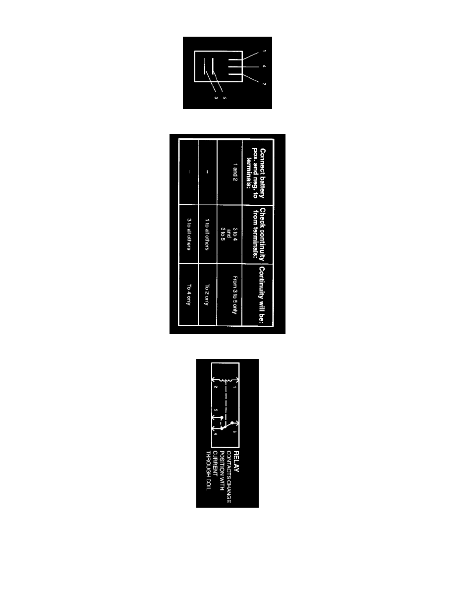
Terminals
Component Testing Procedure
Schematic
Use 73 Digital Multimeter to check for continuity between terminal 2 and all other terminals. If resistance is 5 ohms or less between terminal 2 and any
other terminal, replace the relay. If resistance is greater than 5 ohms, continue the test. Use two jumper wires to connect relay terminal 1 and terminal 3
directly to the positive battery terminal. Set 73 Digital Multimeter in the volts position and check for voltage at terminal 4. If battery voltage is not
indicated, replace the relay. If battery voltage is indicated, connect a third jumper wire to terminal 2 and ground the jumper wire to a known good