
Mountaineer 2WD V6-4.0L VIN K (2007)
6. Remove the outer manual control lever.
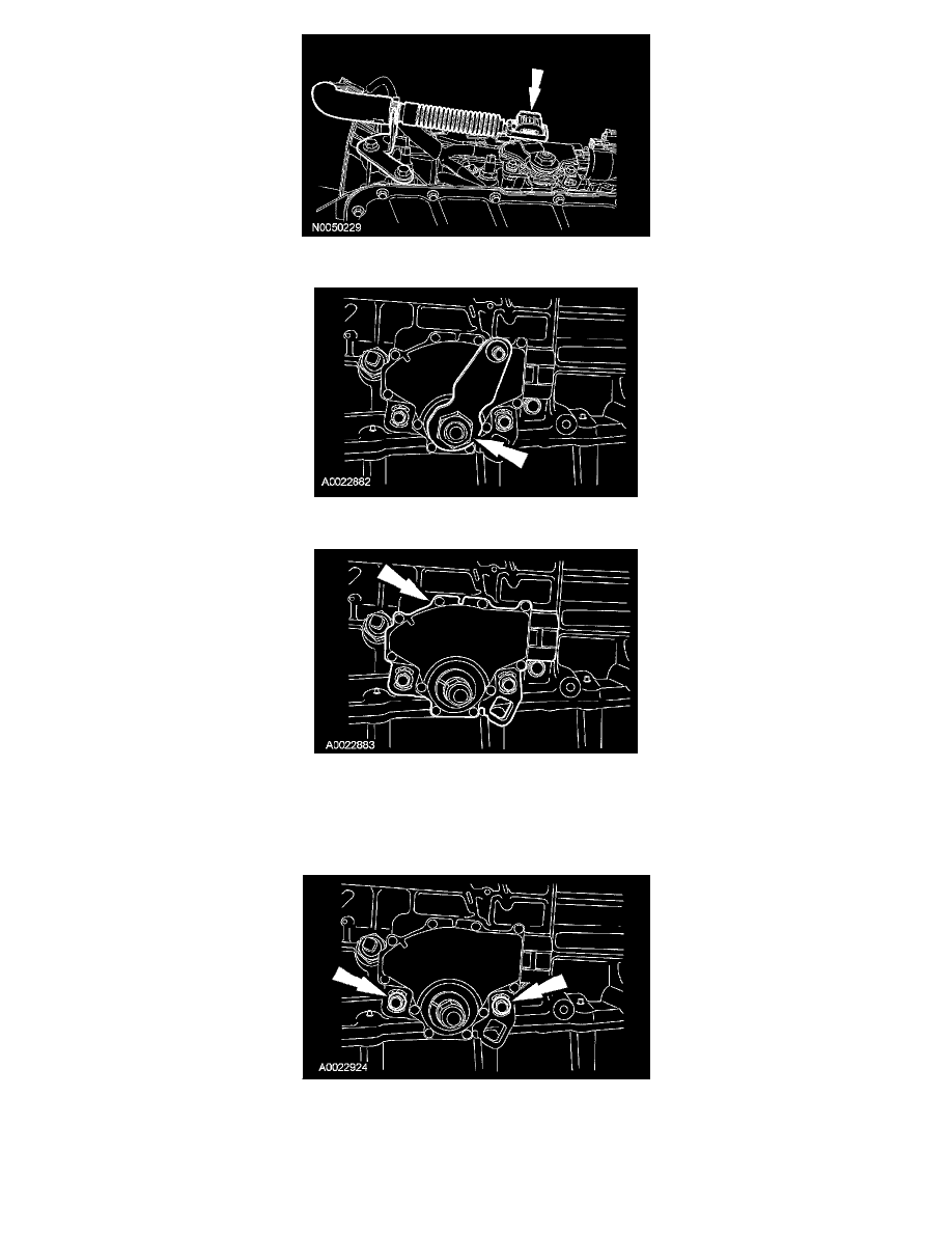
7. Remove the digital TR sensor.
Installation
1. CAUTION: The digital transmission range sensor must fit flush against the boss on the case to prevent damage to the sensor.
Install the digital TR sensor and loosely install the screws.
2. CAUTION: Tightening one screw before tightening the other may cause the sensor to bind or become damaged.
NOTE: The manual lever must be in the NEUTRAL position.
Using the special tool, align the digital TR sensor and tighten the screws in an alternating sequence.