
Mountaineer 2WD V8-4.6L (2010)
DTCs. The module does not allow this code to be cleared or the circuit restored to normal operation until a successful self-test proves that the fault has
been repaired. After the self-test has successfully completed (no on-demand DTCs present), DTC B106E and the associated continuous DTC (the DTC
related to the shorted circuit) automatically clears and the circuit function returns.
When the first or second level is reached, the continuous DTC (associated with the short circuit) sets along with DTC B106E. These DTCs can be
cleared using the module on-demand self-test, then the Clear DTC operation on the scan tool (if the on-demand test shows the fault corrected). The
module never resets the fault event counter to zero and continues to advance the fault event counter as short circuit fault events occur.
If the number of short circuit fault events reach the third level, then DTCs B106F and B1342 set along with the associated continuous DTC. This DTC
cannot be cleared and the module must be replaced.
The SJB FET protected output circuits for the trailer lamp system are the LH and RH trailer stop/turn output circuits.
Inspection and Verification
Trailer Lamps
Inspection and Verification
1. Verify the customer concern.
2. Verify the exterior lighting system of the vehicle is operating correctly. If not, refer to the appropriate pinpoint test.
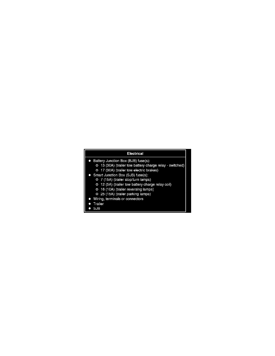
3. Visually inspect for obvious signs of electrical damage.
Visual Inspection Chart
4. If an obvious cause for an observed or reported concern is found, correct the cause (if possible) before proceeding to the next step.
5. NOTE: Make sure to use the latest scan tool software release.
If the cause is not visually evident, connect the scan tool to the Data Link Connector (DLC).
6. NOTE: The Vehicle Communication Module (VCM) LED prove-out confirms power and ground from the DLC are provided to the VCM.
If the scan tool does not communicate with the VCM:
-
Check the VCM connection to the vehicle.
-
Check the scan tool connection to the VCM.
-
Refer to Information Bus, No Power To The Scan Tool, to diagnose no power to the scan tool.
7. If the scan tool does not communicate with the vehicle:
-
Verify the ignition key is in the ON position.
-
Verify the scan tool operation with a known good vehicle.
-
Refer to Information Bus to diagnose no response from the PCM.
8. Carry out the network test.
-
If the scan tool responds with no communication with one or more modules, refer to Information Bus.