
Mountaineer 4WD V6-4.0L VIN E (1999)
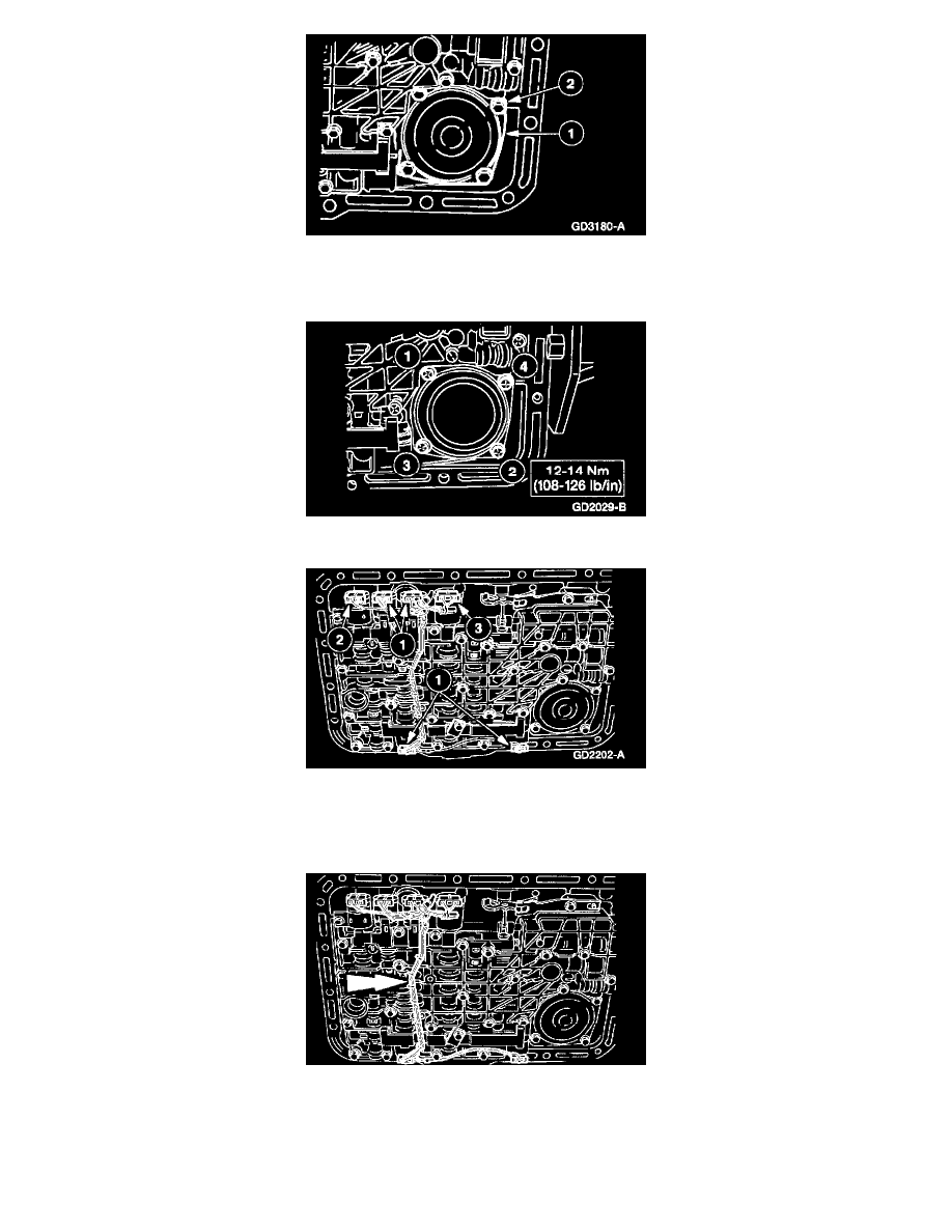
12. Install the low/reverse band servo cover.
1
Install the low/reverse band servo cover and gasket.
2
Loosely install the low/reverse servo piston cover screws.
13. Tighten the servo cover screws in the sequence shown.
14. Connect the six solenoid electrical connectors.
1
Connect SSA, SSB, SSC, and SSD electrical connectors.
2
Connect the Torque Converter Clutch (TCC) solenoid electrical connector.
3
Connect the Electronic Pressure Control (EPC) solenoid electrical connector.
15. CAUTION: Excessive pressure may break the locating pins.
Install the main control valve body wire harness.
-
Align the retaining pins to the holes in the solenoid clamps and press in the main control valve body wire harness guide and protector.