
Mountaineer 4WD V6-4.0L VIN E (1999)
Using a feeler gauge, or a flat, clean drive pinion position shim, measure between the Gauge Block and the Gauge Tube. Record the measurement.
-
Remove the special tools after determining the correct shim thickness.
8. Select the correct thickness drive pinion position shim.
-
New drive pinion position shims are available in 0.762 mm (0.030 in), 0.8128 mm (0.032 in), 0.8636 mm (0.034 in), 0.9144 mm (0.036 in),
0.9652 mm (0.038 in), 1.016 mm (0.040 in), 1.0668 mm (0.042 in), 1.1176 mm (0.044 in), 1.1684 mm (0.046 in), 1.2192 mm (0.048 in), 1.27
mm (0.050 in), and 1.3208 mm (0.052 in) thickness.
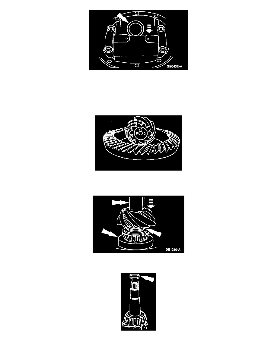
9. The shim selection tool steps identify the correct shim for a ring and pinion with an "O" etching. Optimum depth for each gearset is determined at
the factory and the number is etched, + or -, on the pinion button. If the etched number is positive, subtract that number from the shim thickness
identified by the selection tool steps. If the number is negative, add that number to the selected shim thickness.
10. Install the pinion position shim and the differential pinion bearing.
-
Using the special tool and a suitable press, seat the differential pinion bearing firmly against the pinion position shim.
11. Install a new collapsible spacer.