
Mountaineer AWD V6-4.0L (2008)
Removal and Installation
1. Disconnect the spring lock coupling from the fuel supply tube. For additional information, refer to Fuel Delivery and Air Induction.
2. Remove the intake manifold.
3. Remove the heater hose tube bracket rear bolt.
^
To install, tighten to 23 Nm (17 lb-ft).
4. Remove the heater hose tube bracket front bolt.
^
To install, tighten to 34 Nm (25 lb-ft).
5. Loosen the exhaust manifold-to-EGR system module tube lower fitting and remove the tube.
^
To install, tighten to 34 Nm (25 lb-ft).
6. CAUTION: Use O-ring seals that are made of special fuel-resistant material. Use of ordinary O-ring seals may cause the fuel system to
leak.
Remove the fuel supply tube-to-valve cover bracket bolt, the fuel supply tube bolts and the fuel supply tube. Remove and discard the O-ring seals.
^
Install new O-ring seals and lubricate them with clean engine oil.
^
To install, tighten to 6 Nm (53 lb-in).
7. Detach the spark plug wire retainers and position the spark plug wires aside.
8. Remove the crankcase ventilation tube.
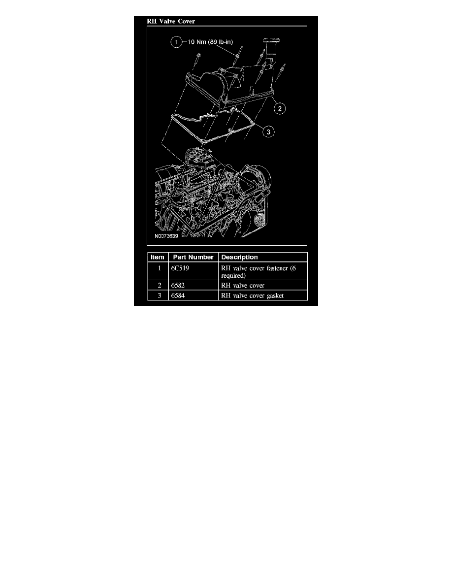
9. Remove the bolts and the valve cover.
^
To install, tighten to 10 Nm (89 lb-in).
10. CAUTION: Do not use metal scrapers, wire brushes, power abrasive discs or other abrasive means to clean sealing surfaces. These tools
cause scratches which make leak paths. Use a plastic scraping tool to remove all traces of the old valve cover gasket.
Clean and inspect the sealing surfaces and the gasket. Install a new gasket if necessary.
11. To install, reverse the removal procedure.