
Mountaineer AWD V6-4.0L VIN K Flex Fuel (2003)
4.
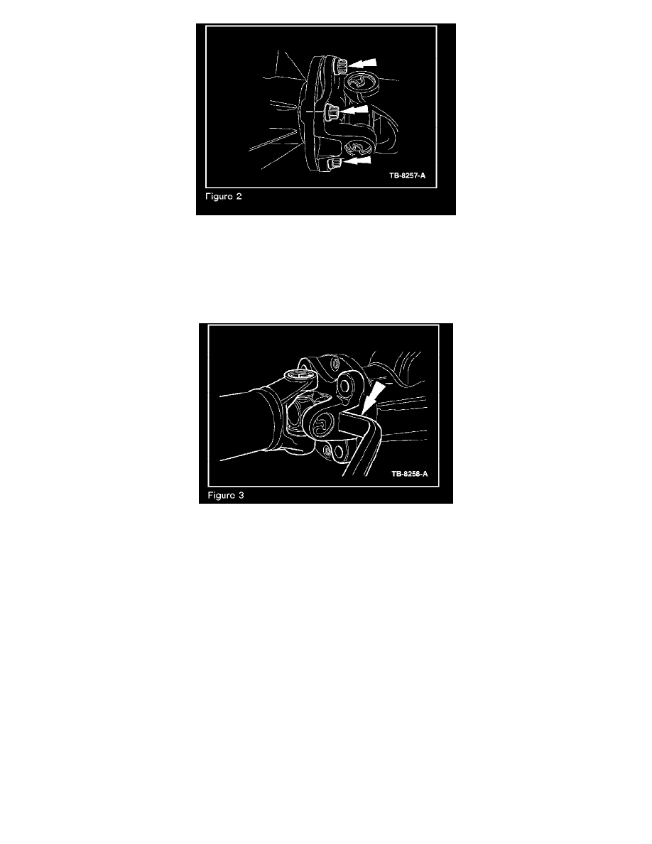
Remove the transfer case rear output flange bolts (Figure 2).
NOTE
THE DRIVESHAFT FLANGE FITS TIGHTLY ON THE AXLE PINION FLANGE PILOT AND THE TRANSFER CASE OUTPUT FLANGE.
DO NOT HAMMER ON THE DRIVESHAFT OR ANY OF ITS COMPONENTS TO DISCONNECT THE DRIVESHAFT FLANGES FROM
THE MATING FLANGES. PRY ONLY IN THE AREA SHOWN WITH A SUITABLE TOOL, TO DISCONNECT THE DRIVESHAFT
FLANGES.
5.
Using a suitable tool, disconnect the driveshaft flanges and remove the driveshaft (Figure 3).
6.
Measure the NEW driveshaft length from u-joint center to u-joint center. Refer to Step 6a or 6b.
a.
Driveshafts measuring LESS than 1194 +/- 1.0 mm must be expanded as follows:
(1)
Place driveshaft on a suitable workbench and firmly secure either flange in a suitable vice.
CAUTION
CAREFULLY SECURE THE DRIVESHAFT TO AVOID DAMAGE TO THE FLANGE.
(2)
Grasp the shaft at the opposing flange with both hands and expand (by pulling) as required to 1194 +/- 1.0 mm.
NOTE
DO NOT USE A BAR OR SIMILAR DEVICE BETWEEN THE FLANGE AND CARDON JOINT.
b.
Driveshafts measuring GREATER than 1194 +/- 1.0 mm must be compressed as follows:
(1)
Place driveshaft on a suitable workbench and firmly secure either flange in a suitable vice.
CAUTION
CAREFULLY SECURE THE DRIVESHAFT TO AVOID DAMAGE TO THE FLANGE.
(2)
Grasp the shaft at the opposing flange with both hands and compress (by pushing) together by hand as required to 1194 +/- 1.0 mm.