
Mountaineer AWD V8-4.6L SOHC VIN W (2002)
NOTE
DO NOT USE A HAMMER OR SIMILAR DEVICE.
THIS MAY CAUSE DAMAGE TO THE SHAFT FLANGE.
7.
To install, align the driveshaft paint markings with companion flange markings, if present.
8.
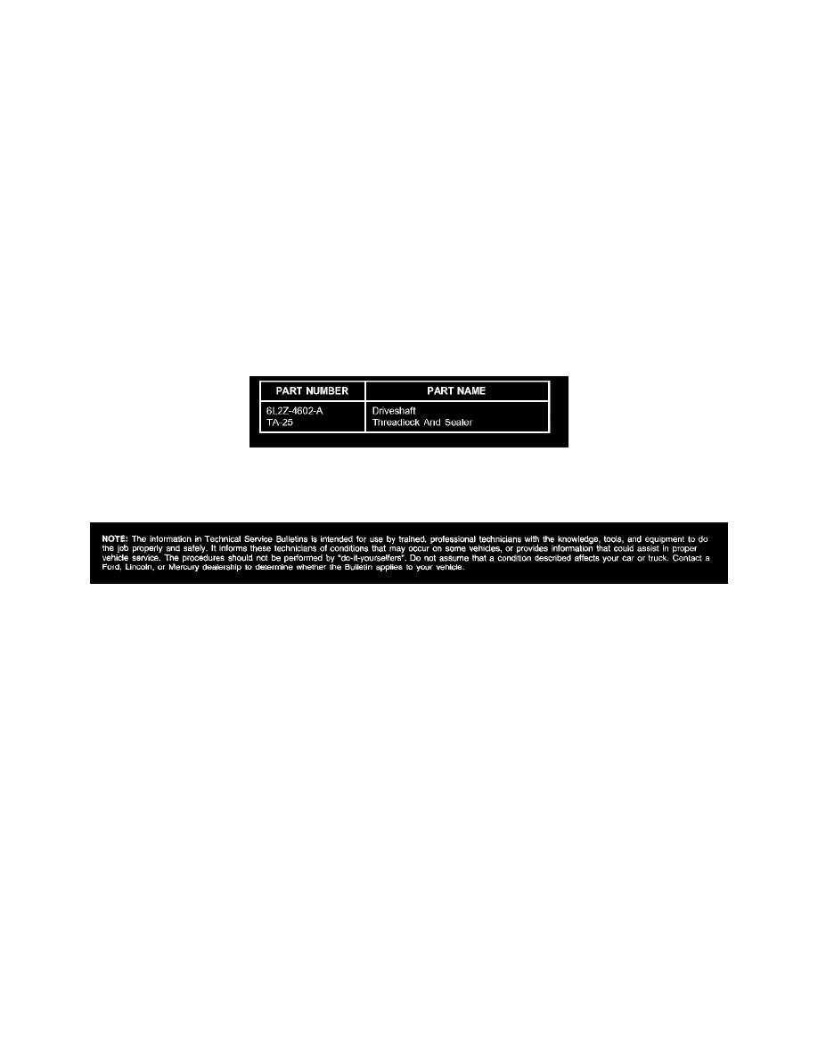
Coat the bolts with Threadlock And Sealer TA-25 meeting Ford specification WSK-M2G351-A5.
NOTE
THE DRIVESHAFT FLANGES FITS TIGHTLY ON THE PINION FLANGE PILOTS. TO ENSURE THE DRIVESHAFT FLANGES SEAT
SQUARELY ON THE PINION FLANGES, TIGHTEN THE DRIVESHAFT FLANGE BOLTS EVENLY IN ACROSS PATTERN.
9.
Support the rear driveshaft.
10.
Install flange bolts at rear axle flange by hand.
11.
Install flange bolts at transfer case flange by hand.
12.
Tighten all driveshaft flange bolts to 76 lb-ft (103 N.m).
13.
Reinstall skid plate, if equipped.
Parts Block
WARRANTY STATUS: Eligible Under Provisions Of New Vehicle Limited Warranty Coverage
Disclaimer