
Mystique L4-122 2.0L DOHC VIN 3 SFI (1995)
14. CAUTION: Only rotate the engine by the crankshaft.
Measure the valve clearances (continued).
-
Rotate the engine by the crankshaft in the direction of engine rotation through another 180 degrees. The sequence of measurements is given by
the firing order: 1-3-4-2.
-
Measure the valve clearances on all other cylinders.
15. NOTE: Only carry out the following two steps if the valves need adjusting.
If the required valve clearances are not obtained, remove the camshafts.
NOTE: A mid-range valve clearance is preferred (intake 0.15 mm, exhaust 0.30 mm).
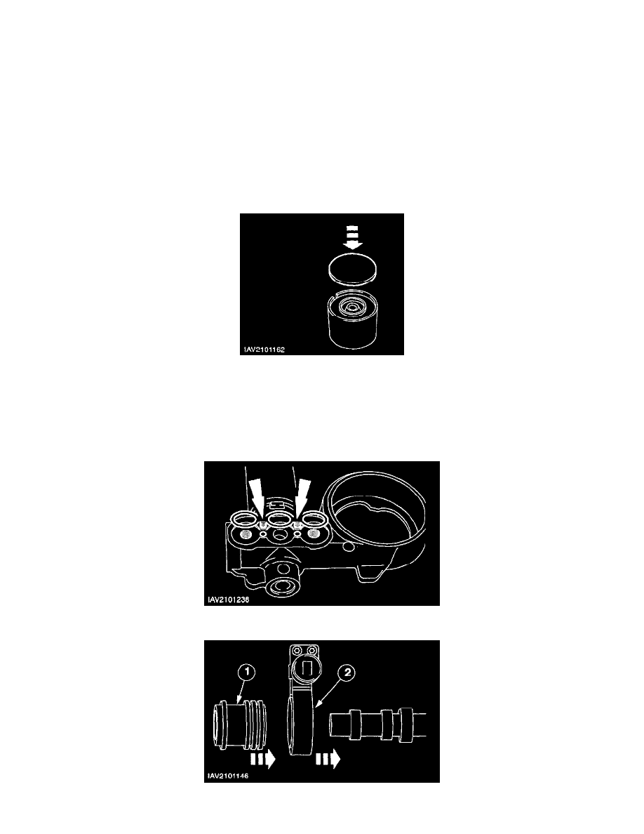
16. NOTE: The number on the shim corresponds to the shim thickness. Example: 222 = 2.22 mm
Measure the required shim thickness.
-
Remove the adjusting shim from the tappets and read off the size from the back (if it is not legible measure it with a micrometer).
-
Measure and insert the shim of the required thickness.
-
Intake valves: required shim thickness = fitted shim thickness + measured valve clearance-0.15 mm.
-
Exhaust valves: required shim thickness = fitted shim thickness + measured valve clearance-0.30 mm.
17. NOTE: Use a thumb to press the locating pins of the gasket into the holes.
Install a new gasket into the oil feed flange.
18. Prepare the exhaust camshaft for installation.