
Mystique L4-122 2.0L DOHC VIN 3 SFI (1995)
Knock Sensor: Description and Operation
Knock Sensor
PURPOSE
The Knock Sensor (KS) is used to sense ignition detonation (ping) and to supply this information to the Powertrain Control Module (PCM). The
PCM uses this input to optimize ignition timing while reducing the occurance of spark detonation and minimizing the amount of Oxides of
Nitrogen (NOx) produced in the exhaust.
CONSTRUCTION
The sensor has a thin circular piezoelectric ceramic disk that is bonded to a metal diaphragm. Electrical connections are made through a two pin
integral connector.
OPERATION
The sensor is designed to resonate at approximately the same frequency as the engine knock (5-6 KHz). As the piezoelectric disk resonates it
converts the sound vibration to an electrical voltage with an equal frequency. This signal is sent directly to the PCM.
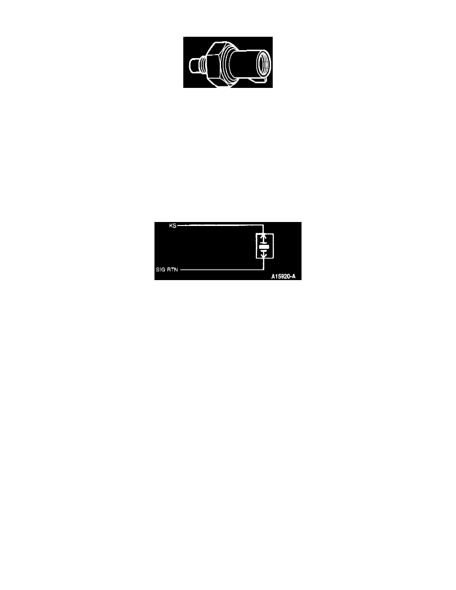
Knock Sensor Circuit
The KS generates its own voltage and does not require a separate power supply. The PCM supplies the sensor ground through the SIG RTN
circuit.
RELATED DIAGNOSTIC TROUBLE CODES
DTC 225 - KS signal was not sensed by the PCM during the Key On Engine Running (KOER) self-test.
NOTE: During the dynamic response (snap throttle) portion of the KOER self-test the PCM advances the timing and checks for a corresponding
output from the KS sensor.