
Mystique V6-153 2.5L DOHC VIN L SFI (1999)
Multiplex Communication Network: Description and Operation
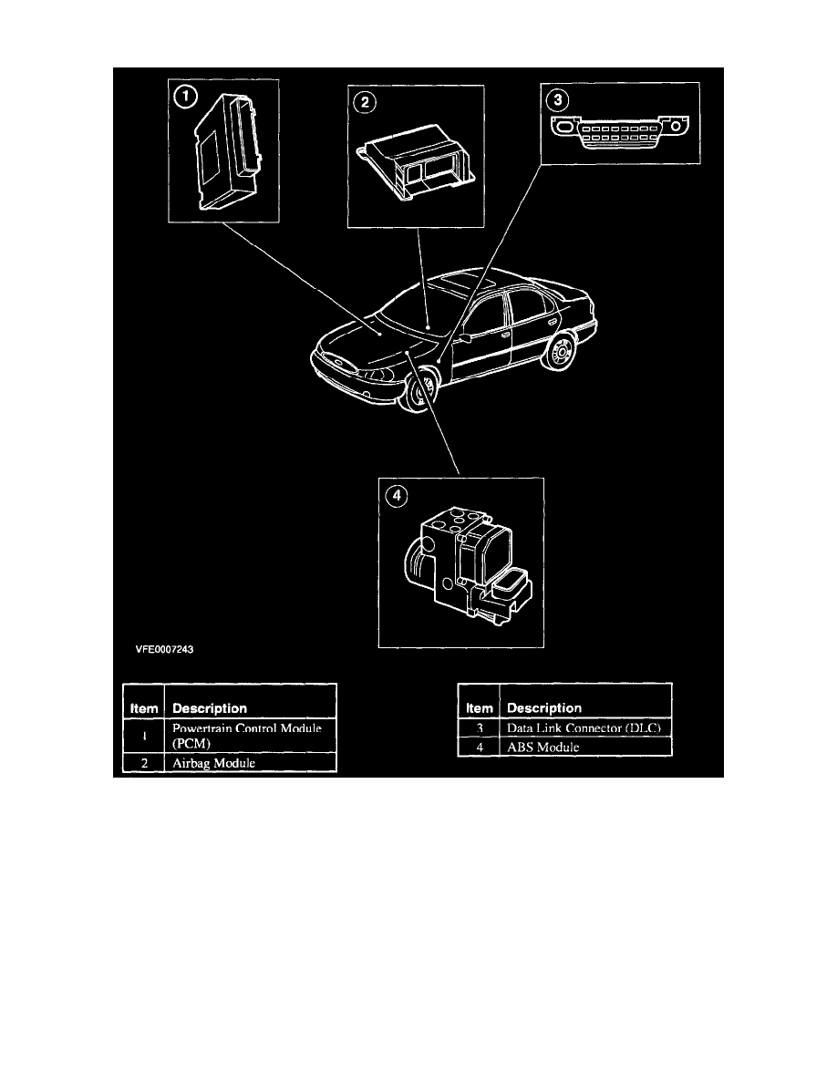
The Powertrain Control Module (PCM) governs all operations in connection with the engine. The PCM is linked to the Data Link Connector (DLC)
through the diagnostic data bus Standard Corporate Protocol (SCP). Data stored in the PCM can be read through the DLC using the NGS diagnostic
tester.
The Passive Anti-theft System (PATS) module is integrated in the PCM. The PATS module contains circuits connecting the vehicle electrical system,
the transceiver module, the vehicle module communications network and the vehicle theft indicator. A microprocessor controls the system functions and
stores the ignition key codes in non-volatile memory. The PATS module can be diagnosed through the data link connector.
The airbag module controls driver and passenger airbag and the pyrotechnical seat belt tensioners. The airbag module is connected to the DLC through
the diagnostic data bus.
The data link connector (DLC) serves as an interface between the modules and the diagnostic tester. This electrical connector is connected to all modules
capable of diagnosis through the diagnostic data bus (SCP or IS09141).
The ABS module controls the antilock braking functions through the brake circuits and is connected to the DLC through the diagnostic data bus
(IS09141). The ABS module is also connected to the diagnostic data bus (SCP) for communicating with the PCM.