
Mystique V6-153 2.5L DOHC VIN L SFI (1999)
Headlamp Switch: Testing and Inspection
Component Testing Instructions
Component testing procedures are provided to determine whether a component is good or bad.
Testing information for each component includes a schematic with component terminal locations and step-by-step test procedures. Component
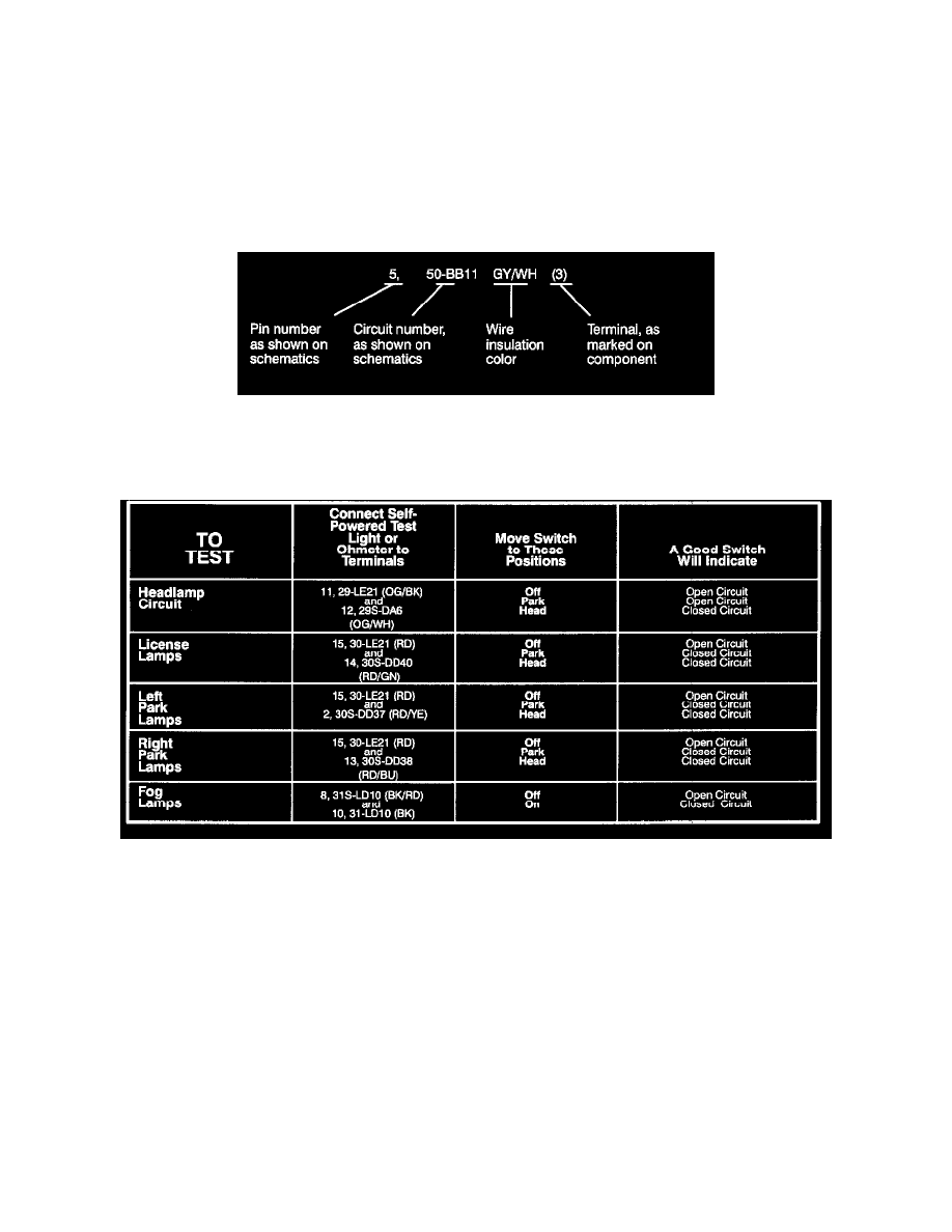
terminals are identified by:
1. the circuit number of the wires that connect to that terminal,
2. the wire insulation color; and
3. letters or numbers that may be marked on the component.
The component connector MUST BE REMOVED before testing. To test a single circuit within the component, select that circuit under the column
TO TEST. If you wish to test the complete component, perform all tests.
Connect the tester to the terminals in the second column and operate the component in the third column.
Component Testing Procedure