
Sable V6-182 3.0L (1986)
Refrigerant Pressure Sensor / Switch: Testing and Inspection
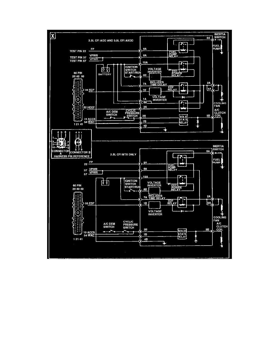
Type 22
Electric engine cooling fan wiring diagram. Type 22
Refer to Fig. 23, during the following procedure. It should be noted that the fan controller has an internal circuit protection that will open the fan circuit
if the fan relay coil is shorted.
1.
With the ignition switch in the OFF position, disconnect integrated controller electrical connector. Using a suitable digital voltmeter, measure
voltage between battery ground terminal and pins 1A, 4A and 7A of the integrated controller electrical connector.
a.
If voltmeter readings are 10 1/2 volts or more, proceed to step 2.
b.
If voltmeter readings are less than 10 1/2 volts, check circuit and repair as necessary.
2.
With ignition switch in the OFF position and integral controller 10 pin electrical connector disconnected, connect a jumper wire between
integrated controller electrical connector pins 1A and 2A.
a.
If fan motor is now operating, proceed to step 3.
b.
If fan motor is not operating, proceed to step 4.
3.
With ignition switch in OFF position and integral controller electrical connector connected, disconnect 60 pin processor. Place ignition switch in
the ON position and note if cooling fan is operating at low speed.
a.
If cooling fan is not operating at low speed, proceed to step 5.
b.
If cooling fan is operating at low speed, proceed to step 6.