
Sable V6-232 3.8L (1988)
Fuel Gauge: Description and Operation
GENERAL SYSTEM DESCRIPTION
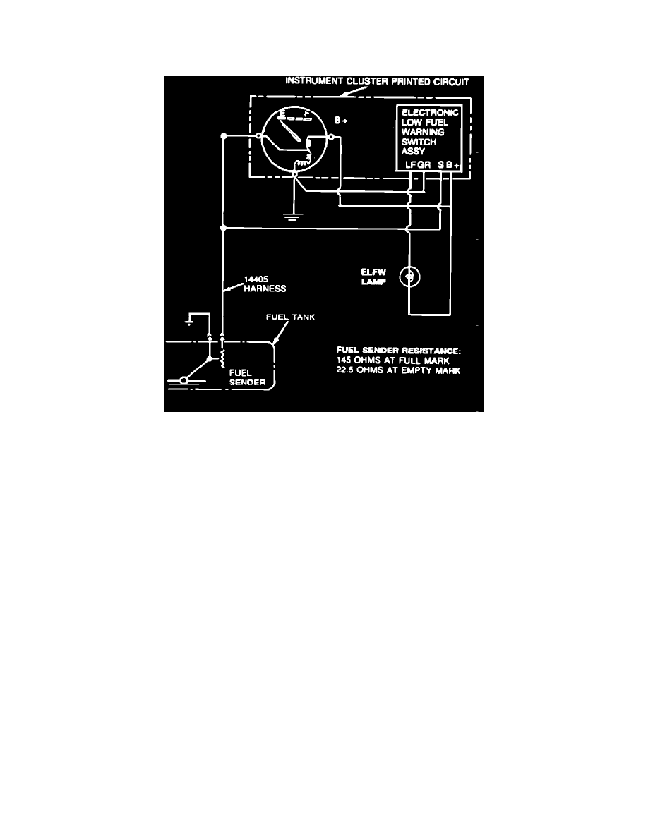
Fuel Indicator System Wiring Schematic
The fuel level indicator system is a magnetic-type indicating system, which consists of the sending unit located in the fuel tank, and a fuel gauge located
in the instrument cluster.
The sending unit changes resistance according to the level of fuel in the fuel tank, which varies the current flow through the gauges. The pointer position
varies proportionally to the current flow. In this system, the sending unit resistance is low when the fuel level is low and high when the fuel level is high.
The pointer of the magnetic gauge remains in position when ignition is in the OFF position.
NOTE: An electronic damping circuit has been added to dampen out fluctuating fuel signals from the sender. The circuit is located on back of the
cluster and is wired to the fuel gauge.
FUEL SENDER
The fuel sending unit is made up of a float in the fuel tank with a lever attached to a variable resistor. When the fuel level is low the variable resistor is
positioned by the float to a low resistance, and when then fuel level is high the variable resistor is positioned by the float to a high resistance.
LOW FUEL LEVEL WARNING SWITCH ASSEMBLY
The low fuel level warning switch assembly is a solid state device without a housing or wiring connector it is designed to provide a warning when the
fuel tank is approximately one-eighth full. The assembly is mounted directly to the instrument cluster backing plate and makes electrical connection
directly with the cluster printed circuit pads.