
Sable V6-232 3.8L (1988)
Malfunction Indicator Lamp: Description and Operation
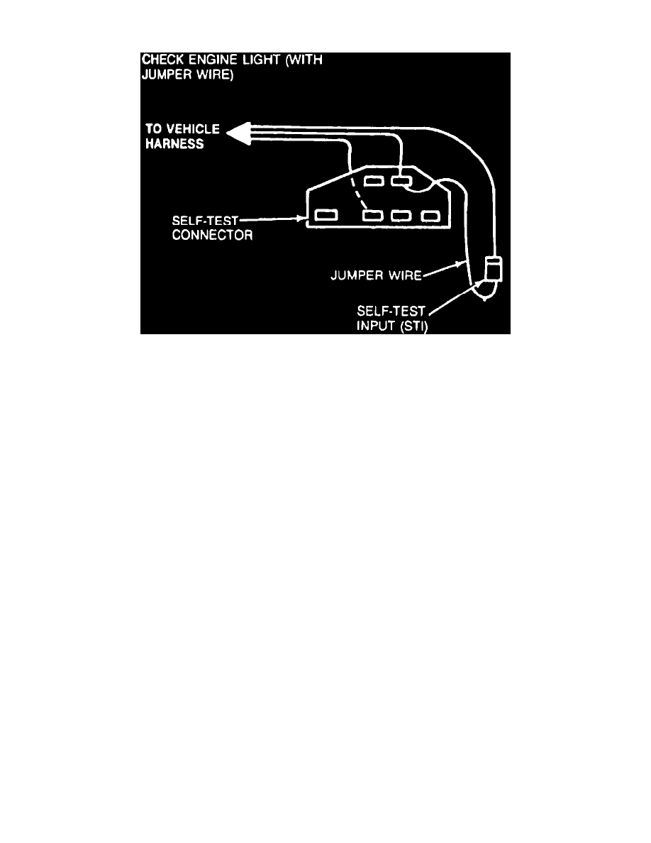
Fig. 1 Jumper wire connections for resetting Check Engine Lamp.
This lamp will be illuminated when the ignition switch is placed in the On position. After engine is started the lamp should go off, unless a problem
has been detected by the EEC-IV system. After diagnosis and repair, the Check Engine/MIL lamp will automatically reset when stored codes are cleared
from the EEC-IV system memory. After diagnosis and repair, EEC-IV memory may be cleared of stored codes as follows:
1.
With ignition switch in the Off position, connect a jumper wire between Self Test and Self Test Input (STI) connectors, Fig. 1.
On 1987---89 Ford Crown Victoria, Mercury Grand Marquis and Lincoln Town Car models, the Self Test and STI connectors are gray in color and are
located on the front of left hand fender apron, near the Electronic Engine Control (EEC) relay. On 1987---89 Ford Mustang models, the Self Test and
STI connectors are gray in color and are located on the left hand fender apron. On 1987---89 Ford Escort, Tempo and Mercury Lynx and Topaz, the Self
Test connector is gray in color and the STI connector is black in color and they are both located on the right hand fender apron near the front of the strut
tower. On 1987---89 Ford Taurus and Mercury Sable, the Self Test and STI connectors are gray in color and are located on the right hand fender apron
near the front of the engine in the area of the AIR pump and alternator. On 1987---88 Ford Thunderbird and Mercury Cougar, the Self Test and STI
connectors are gray in color and are located on the left hand fender apron near the strut tower. On 1987 Lincoln Continental and 1987---89 Lincoln Mark
VII, the Self Test and STI connectors are gray in color and are located on the right hand side of fender apron near the ignition coil. On 1988---89 Lincoln
Continental, the Self Test and STI connectors are attached to the Electronic Control Assembly, which is located in the engine compartment at the center
of the firewall below the TFI ignition module.
2.
Position ignition switch in On position, then disconnect jumper wire from test connector terminals. Disconnect jumper as soon as check engine
lamp starts flashing.