
Sable V6-232 3.8L (1988)
column shaft.
9.
On all models, remove steering shaft assembly from steering column.
10.
Remove two bolts attaching lock cylinder housing to outer tube flange bracket, then rotate ignition key to Start position and pull actuator interlock
out of clearance hole in tube.
11.
Remove ignition lock drive gear and actuator.
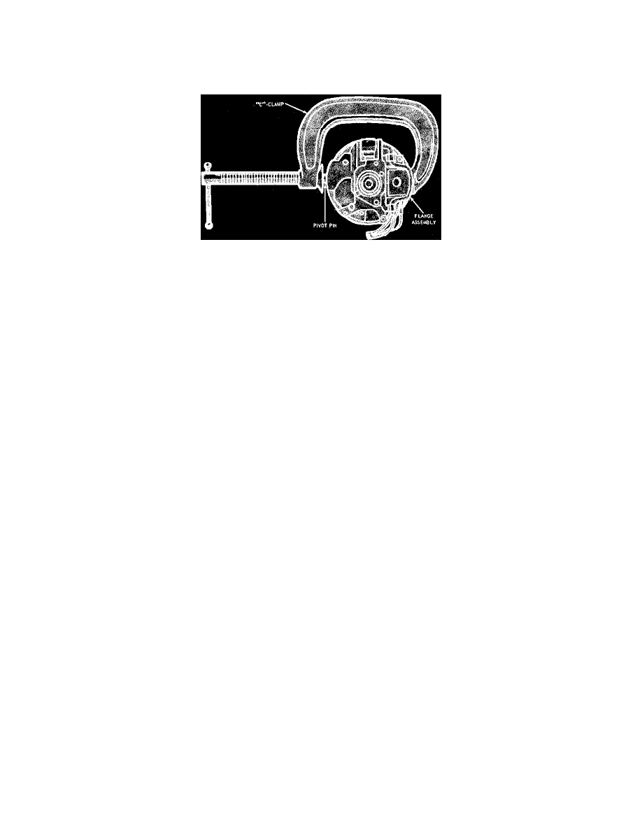
Fig. 17 Installing flange assembly pivot pins
Installation
1.
Position lock cylinder housing on upper steering column flange bracket. Place key in Start position to locate actuator interlock through clearance
hole in outer tube. Install and torque two bolts attaching lock cylinder housing to bracket to 12 to 20 ft. lbs.
2.
Install steering shaft assembly into steering column tube.
3.
Install upper casting assembly with tilt spring in position, over end of shaft and down into lock cylinder ears making certain lock lever is latched
into the top tilt position.
4.
Install tilt pivot pins through lower casting holes and into upper casting using a C-clamp, Fig. 17. Pivot pins must be flush with outer casing
surface.
5.
Install C-clip ring on upper shaft groove above bearing.
6.
Install upper bearing plate and conical spring. Press spring onto upper shaft until spring snaps into groove.
7.
Install turn signal switch and windshield wiper/washer switch.
8.
On column shift models, install shift cane assembly.
9.
On all except Ford & Mercury full size, 1982---83 Mark VI & Town Car, install lower U-joint shaft assembly into lower steering shaft. Install
attaching bolt with bolt head against concave portion of tube. Torque nut and bolt to 35 to 45 ft. lbs.
10.
On all models, install steering column, then install steering wheel.