
Sable V6-232 3.8L (1988)
Differential Case: Adjustments
Differential Case Installation
1.
Apply suitable axle lubricant to differential bearing bores.
2.
Place differential bearing cups on bearings, then set differential assembly in axle housing. If ring gear and pinion gear have punch marks,
assemble ring gear in carrier so that marked tooth on pinion is indexed between the marked teeth of ring gear.
3.
On 6.75 inch axles, install differential gauge disc .2 inch (5.0 mm) thick on left side (tool No. T78P-4136-B1) and .3 inch (7.6mm) thick on right
side (tool No. T78P-4136-B2). Install bearing caps using reference marks made during removal. Install bolts and torque to 30 ft. lbs. Install
adjuster tool No. T78P-4136-B into left side axle tube and torque to 40 inch lbs. to position differential case towards pinion side.
4.
Install a .265 inch shim on left side of case, then install bearing cap and tighten bolts finger tight. Install progressively larger shims on right side of
case until the largest shim selected can be installed with a slight drag. Install bearing cap and torque all bolts to 70---85 ft. lbs.
5.
On all axles, rotate differential several turns in either direction to ensure free rotation and to seat bearings.
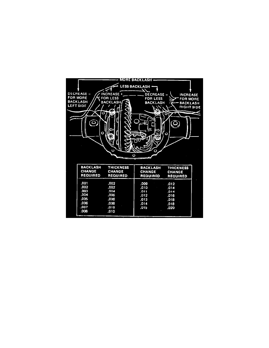
Fig. 11 Rear axle backlash adjustment
6.
On 1982---87 axles, proceed as follows:
a. Mount suitable dial indicator on axle housing cover flange, then measure ring gear backlash. If backlash is within specifications, proceed to
step f. If backlash is not within specifications, proceed to step c. If backlash is zero, proceed to next step.
b. If backlash measured above is zero, add .020 inch (.5 mm) to right side of case and subtract .020 inch (.5 mm) from left side of case, then
recheck backlash. If backlash is now within specifications, proceed to step d.
c. If backlash is not within specifications, correct backlash by increasing thickness of one shim and decreasing thickness on the other shim by
the same amount. Refer to Fig. 11, for approximate shim change.
d. Install shims and bearing caps. Torque bearing cap bolts to 70---85 ft. lbs., then rotate differential case assembly several turns in both
directions.
e. Check backlash. If backlash is within specifications, proceed to step f. If not within specifications, repeat step c.
f.
Increase both left and right side shims by .006 inch to provide proper differential bearing preload. Ensure shims are fully seated and the case
assembly turns freely.
g. Using suitable white marking compound applied to ring gear, check tooth mesh contacting pattern. Tooth mesh contacting pattern can be
improved by installing the propeller shaft and axle assemblies and rotating both tires in the drive and coast direction.
h. Contacting pattern should be within the primary area of the ring gear tooth surface avoiding narrow contact with the outer perimeter of tooth.
Inspect pattern on the drive (pull) side of the ring gear. If serious error is determined, recheck pinion shim selection.
7.
Install axle housing cover, driveshaft and axle assemblies. Refer to ``Rear Axles, Propeller Shaft & Brakes'' section for procedures.
8.
Fill rear axle assembly with suitable axle lubricant. On models equipped with 7.5 and 8.5 inch Traction-Lok differentials, subtract 4 ounces of
axle lubricant and replace with 4 ounces of Friction Modifier C8AZ-19546-A or equivalent.