
Sable V6-232 3.8L (1988)
b. Rotate pinions and thrust washers until pinion gear holes align with pinion shaft holes in the case.
c. Install pinion shaft in case while aligning pinion shaft lock pin hole with hole in case, then install lock pin.
d. Position lefthand case on righthand case, then align reference marks and press two halves together in suitable vise.
e. Install ring gear on case and install new bolts. If bolts show a green coating on the threaded area, install bolts as is and torque to 45---60 ft.
lbs. If no coating is noticed, coat bolt threaded area with suitable thread locking compound, then install bolts and torque to 45---60 ft. lbs.
2.
On all except 6.75 inch axles, install replacement ring gear (if removed). Apply suitable locking compound to new bolts and torque to 70---85 ft.
lbs.
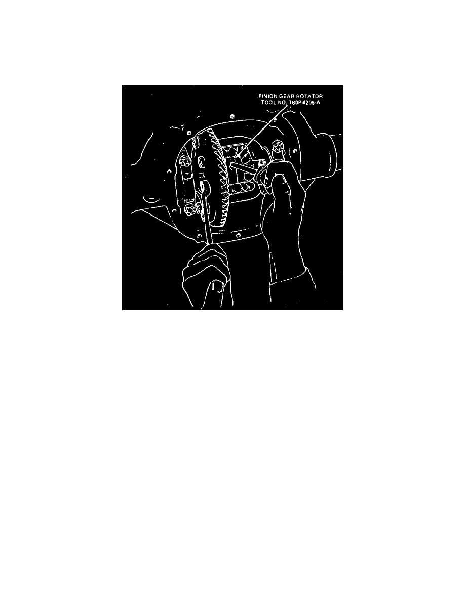
Fig. 8 Pinion gear removal & installation. Ford Traction-Lok
TRACTION-LOK LIMITED SLIP DIFFERENTIAL
Ford Type
1.
Apply suitable lubricant to clutch plates, then install left side gear, clutch pack and new shim into differential case. Repeat procedure for righthand
side.
2.
Install pinion gears and thrust washers 180° apart and in contact with side gears.
3.
Align gears with pinion shaft bore, Fig. 8, using 12 inch socket extension inserted in pinion shaft rotator.
4.
Install ``S'' shaped preload spring into differential using soft faced hammer.