
Sable V6-232 3.8L (1988)
1.
Ground pin G and connect a jumper wire between pins B and 1. Connect a 12-volt test lamp between pin L and ground.
2.
Supply power to pin B. The test lamp should not light.
3.
Momentarily connect pin S to B. The test lamp should come on.
4.
The test lamp should go off under the following conditions:
a.
Terminal S is momentarily connected to pin B.
b.
Jumper wire between pins B and I is removed.
c.
Approximately 10 minutes have elapsed from the time the switch was turned on.
Grid Wire Test
1.
Using a strong lamp inside the vehicle, visually inspect the wire grid from the outside. A broken grid wire will appear as a brown spot.
2.
Run the engine at idle. Set the control switch to ON. The indicator lamp should come on.
3.
Working inside the vehicle with a 12-volt DC voltmeter such as Rotunda Digital Volt Ohm Meter 007-00001 or equivalent, contact the broad
red-brown strips on the rear window positive lead to battery side and negative lead to ground side. The meter should read 10-13 volts. A lower
voltage reading indicates a loose ground wire (pigtail) connection at the ground attaching screw.
4.
Contact a good ground point with the negative lead of the meter. The voltage reading should not change.
5.
With the negative lead of the meter grounded, touch each grid line of the heated rear window at its midpoint with the positive lead. A reading of
approximately 6-volts indicates that the line is good. A reading of 0-volts indicates that the line is broken between the midpoint and the B+ side of
the grid line. A reading of 12-volts indicates that the circuit is broken between the midpoint of the grid line and ground.
REMOVAL AND INSTALLATION
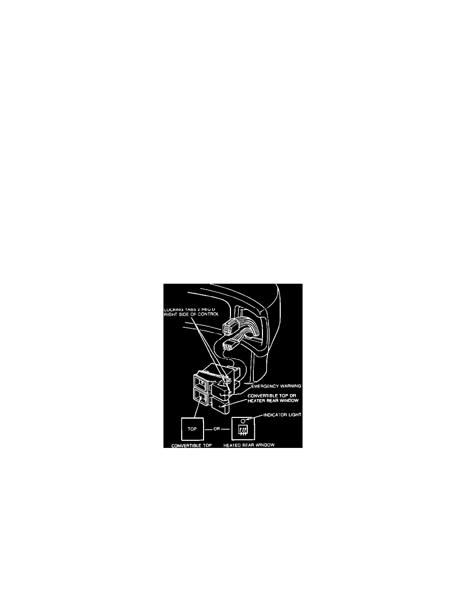
Control Assembly
1.
Disengage the two locking tabs on the RH side of control by pushing the tabs in with a small screwdriver and pulling on the RH side of the control.
2.
Using a screwdriver, pry the LH side of the control out of the instrument panel.
3.
Pull the control completely out of the opening and disconnect the two connectors.
4.
To install, install the two connectors to the control and insert control into opening in instrument panel until the locking tabs on both sides of the
control snap in place.
Relay/Timer