
Sable V6-232 3.8L (1988)
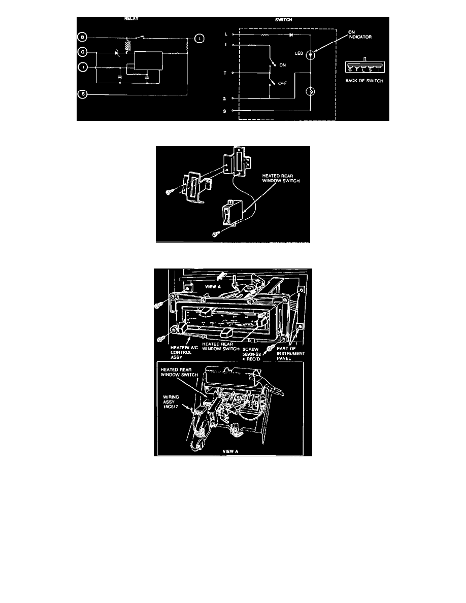
FIGURE 5 - Control Assembly Electrical Schematic-Thunderbird/Cougar with EATC
FIGURE 6 - Switch Assembly-Mark VII
FIGURE 7 - Switch Assembly-Thunderbird/Cougar
1988 Mark VII - Thunderbird/Cougar - Mustang
36-86-5
Window, Rear-Defroster
36-86-6
1.
Disengage the two locking tabs on the RH side of control by pushing the tabs in with a small screwdriver and pulling on the RH side of the control.
2.
Using a screwdriver, pry the LH side of the control out of the instrument panel.
3.
Pull the control completely out of the opening and disconnect the two connectors.
4.
To install, install the two connectors to the control and insert control into opening in instrument panel until the locking tabs on both sides of the
control snap in place.